IS620P User Manual Chapter 3 Wiring of Servo System
- 65 -
Table 3-20 Denition of DB9 terminal pins at PC side
Pin No. Pin Description Terminal Pin layout
2 PC-RXD PC receiving end
3 PC-TXD PC sending end
5
C
GND Ground
Housing PE Shield
Figure 3-12 Communication cable appearance
Table 3-21 Pin denition of the communication cable
RJ45 at Servo Drive Side (A) DB9 at PC Side (B)
Signal Pin No. Signal Pin No.
GND 8 GND 5
RS232-TXD 6 PC-RXD 2
RS232-RXD 7 PC-TXD 3
PE (shield) Housing PE (shield) Housing
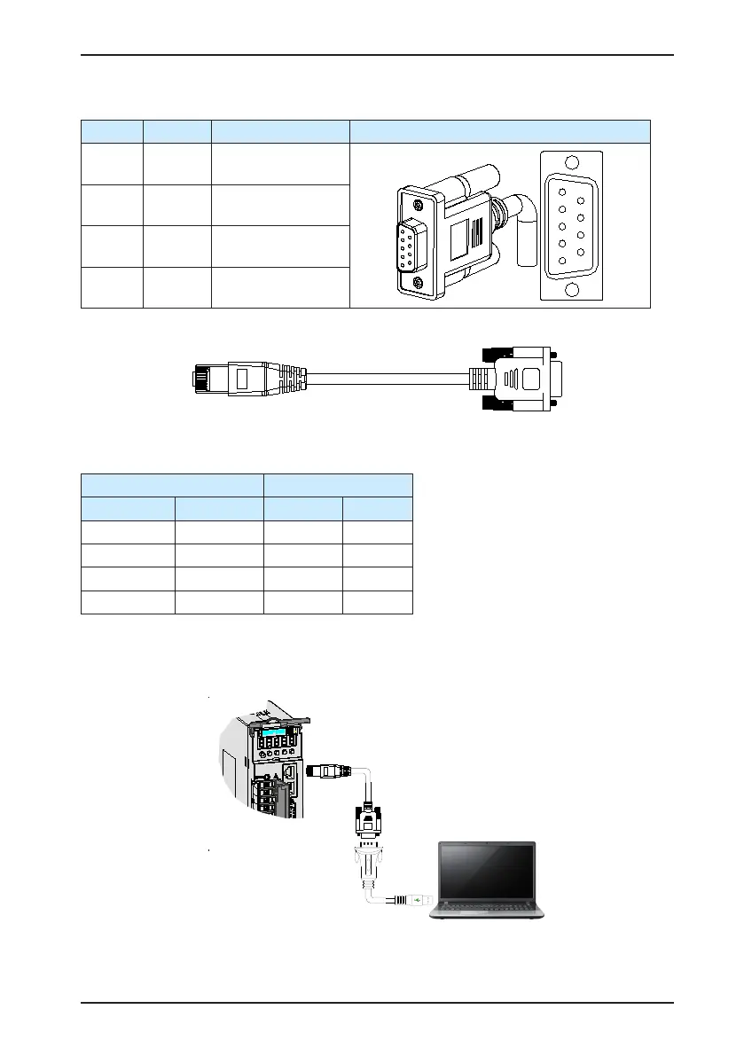
If the host controller provides only the USB interface, use the serial-to-USB cable for
conversion.
Figure 3-13 Serial-to-USB conversion diagram
The recommended cable is as follows:

 Loading...
