Chapter 3 Wiring of Servo System IS620P User Manual
- 64 -
The description of brake output time sequence is as follows:
When the servo is ON, wait for the operation delay time of the brake (as set in H02-09) before
sending commands to the servo drive. Otherwise, the servo drive does not respond.
When the servo is OFF, the brake signal is immediately sent out. The servo motor is still ON
within the delay time as set in H02-10, to prevent heavy objects from falling due to gravity.
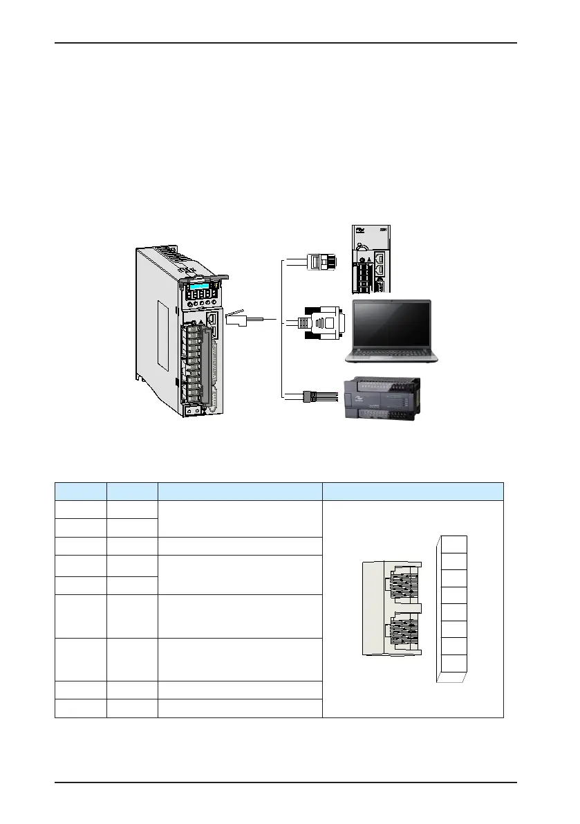
3.4 Communication Signal Wiring
Figure 3-11 Communication wiring
L1C
L2C
R
S
T
-
P
+
D
C
U
V
W
CN3
CN4
CN1
CN2
CN3 and CN4 are two same communication signal terminals connected in parallel. Do not
connect wires to the reserved pins.
Table 3-19 Communication signal terminal pin denition
Pin No. Pin Description Terminal Pin layout
1 CANH
CAN communication port
2 CANL
3 GNDG CAN communication ground
4 RS485+
RS485 communication port
5 RS485-
6
RS232-
TXD
RS232 sending end, connected
to the receiving end of the host
controller
7
RS232-
RXD
RS232 receiving end, connected
to the sending end of the host
controller
8 GND Ground
Housing PE Shield
The following table lists denition of DB9 terminal at the PC side.

 Loading...
