IS620P User Manual Chapter 4 Running and Commissioning
- 85 -
•
The signal cables and power cables must be laid separately with the distance at least above 30
cm.
•
When the signal cable is not long enough and an extension cable needs to be connected, ensure
that the shield is connected reliably and the shielding and grounding are reliable.
•
+5V is referenced to GND, and +24V is referenced to COM-.
•
The current must not exceed the maximum allowable value. Otherwise, the servo drive cannot
work properly.
4.2.2 Function Code Setting of the Speed Control Mode
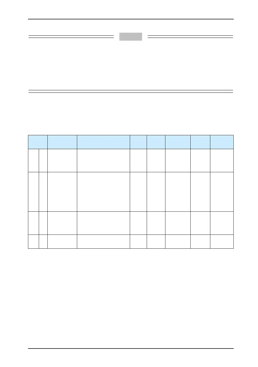
1. Speed reference input setting
a. Speed reference source
In the speed control mode, there are two speed reference sources, source A and source B.
Function
Code
Parameter
Name
Setting Range Unit Default
Effective
Time
Property
Control
Mode
H06 00
Main speed
reference A
source
0: Digital setting (H06-
03)
1: AI1
2: AI2
- 0 Immediate At stop S
H06 01
Auxiliary
speed
reference B
source
0: Digital setting (H06-
03)
1: AI1
2: AI2
3: 0 (No function)
4: 0 (No function)
5: Multi-speed reference
- 1 Immediate At stop S
H06 03
Keypad
setting value
of speed
reference
-6000 to 6000 rpm 200 Immediate
During
running
S
H06 04
Jog speed
setting value
0–6000 RPM rpm 100 Immediate
During
running
S
•
The digital setting is performed on the keypad, and the speed set in H06-03 is used as the
speed reference.
•
The analog setting means that the externally input analog voltage signal is converted to
the speed reference signal.

 Loading...
