Chapter 3 Wiring of Servo System IS620P User Manual
- 48 -
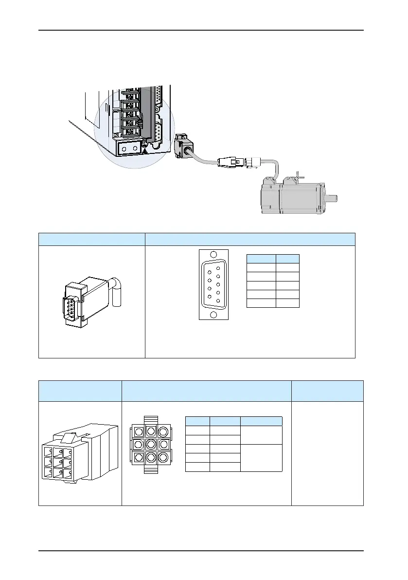
3.2 Connecting Servo Motor Encoder Signals
Figure 3-7 Example of connecting encoder signals
Table 3-8 Connectors of encoder cables on servo drive side
Connector Appearance Terminal Pin Layout
Pin No. Signal
1 PS+
2 PS-
7 +5V
8 GND
Housing PE
Recommendation:
Plastic housing of plug on cable side: DB9P (TELE-DATA
COM), black housing
Core: DB9P plug (TELE-DATA COM), blue glue
Table 3-9 Connectors of encoder cables at servo motor side
Connector Appearance Terminal Pin Layout
Frame Size of
Adaptable Motor
9-pin plug
Pin No. Signal
3 PS+
Twisted-pair
6 PS-
9 +5V
8 GND
7 Shielded
Recommendation:
Plastic housing: AMP 172161-1:
Terminal: AMP 770835-1
40
60
80

 Loading...
