IS620P User Manual Chapter 4 Running and Commissioning
- 81 -
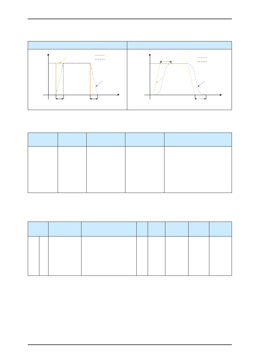
Table 4-2 Different lter effects of two position reference types under the average lter
Rectangular Position Reference Ladder Position Reference
Position
reference
Time (T)
P
Before filter
After filter
Average filter time
05-06
H
05-06H
After filter
Average filter time
Before filter
Time (T)
P
Before filter
After filter
Average filter time
05-06
H
Average filter time
05-06H
Position
reference
After filter
Before filter
4. Clearing position deviation
Set the function FunIN.35 for a DI to determine whether to clear the position deviation.
Function No.
Function
Name
Description Setting Remarks
FunIN.35 ClrPosErr
Position deviation
cleared
Valid: Clear
Invalid: Not clear
It is recommended that this
function be allocated to DI8
or DI9 and the logic of the
corresponding terminal be set
to edge valid. If you set the
logic to level valid, the servo
drive forcibly changes it to edge
logic internally.
5. Frequency-division output
This parameter is used to select the pulse output source. The reference pulse synchronous
output is used in the synchronous control scenario.
Function
Code
Parameter
Name
Setting Range Unit Default
Effective
Time
Property
Control
Mode
H05 38
Servo pulse
output source
0: Encoder frequency-
division output
1: Reference pulse
synchronous output
2: Frequency-division
and synchronous output
forbidden
- 0
Power-on
again
At stop P
The servo drive performs frequency division on the pulses from the encoder based on the
value of H05-17 and then outputs the processed pulses via the frequency-division output
terminal. The value of H05-17 corresponds to the pulses from PAO/PBO at each revolution
(before 4-frequency multiplication). In other words, the nal output pulses of PAO/PBO is four
times of the setting value of H05-17.

 Loading...
