IS620P User Manual Chapter 3 Wiring of Servo System
- 41 -
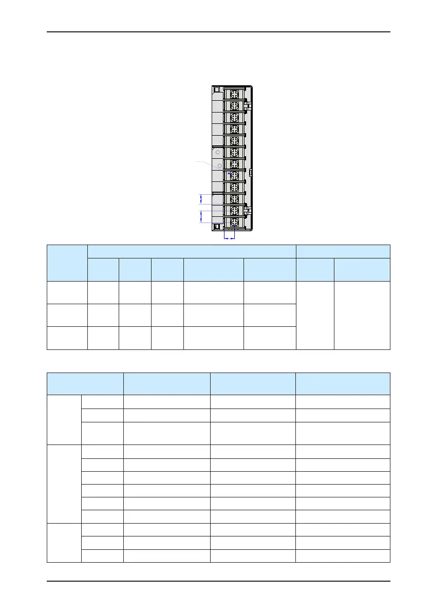
3.1.2 Recommended Models and Specications of Main Circuit Cables
Figure 3-3 Dimension drawing of the servo drive terminal block
ZY
X
Screw
L1C
R
S
T
L2C
-
P
D
C
+
U
V
W
Servo
Drive Size
Main Circuit Terminal PE Grounding Terminal
X (mm) Y (mm) Z (mm) Screw
Tightening
Torque (N·m)
Screw
Size
Tightening
Torque (N·m)
SIZE A 6.8 7.6 6.3
M3 combination
screw
0.4–0.6
M4 0.6–1.2SIZE C 8 8.2 7
M3 combination
screw
0.4–0.6
SIZE E 9 13 10
M4 combination
screw
0.7–1.0
Table 3-2 Rated input and output currents of IS620P series servo drive
Servo Drive Model
(IS620P□□□□I)
Rated Input Current
(A)
Rated Output Current
(A)
Max. Output Current (A)
SIZE A
S1R6 2.3 1.6 5.8
S2R8 4.0 2.8 10.1
S5R5
7.9 (single-phase)/3.7
(three-phase)
5.5 16.9
SIZE C
S7R6 5.1 7.6 17
S012 8.0 11.6 28
T3R5 2.4 3.5 8.5
T5R4 3.6 5.4 14
T8R4 5.6 8.4 20
T012 8.0 11.9 23.8
SIZE E
T017 12.0 16.5 42
T021 16.0 20.8 55
T026 21.0 25.7 65

 Loading...
