Chapter 3 Wiring of Servo System IS620P User Manual
- 40 -
Terminal
Symbol
Terminal
Name
Terminal Function
and
Common DC
bus terminal
For common DC bus connection when multiple servo drives are used
in parallel.
U, V, W
Servo motor
connection
terminals
Connect to U, V and W phases of the servo motor.
PE
Grounding
terminal
Two grounding terminals are respectively connected to the power
supply grounding terminal and the servo motor grounding terminal.
The entire system must be grounded.
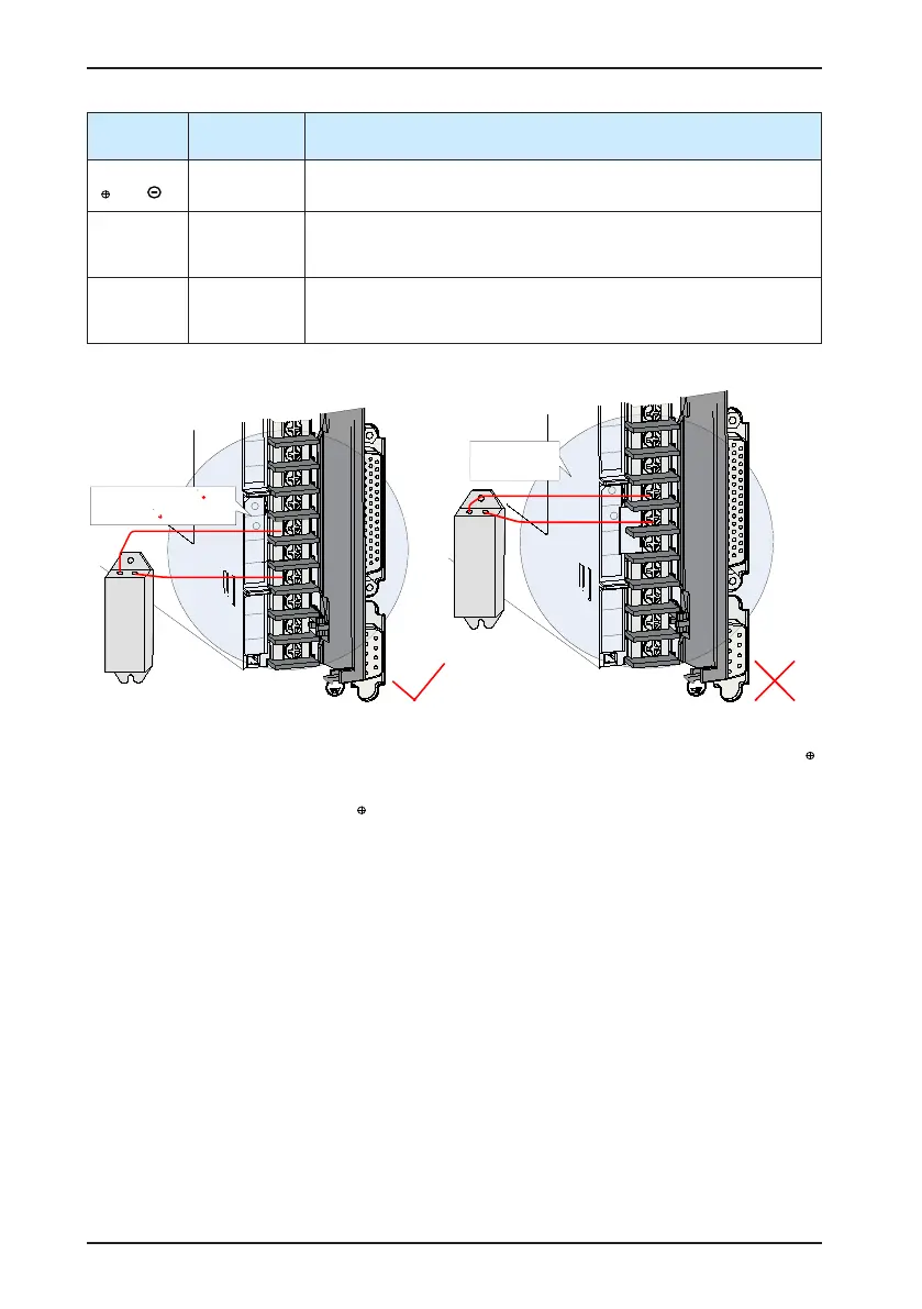
The following gures show the correct and wrong wiring of the external regen resistor.
CN1
CN2
U
V
W
-
P
+
D
C
R
S
T
Remove the jumper between and
D, and connect an external regen
resistor between and C.
CN1
CN2
U
V
W
-
P
+
D
C
R
S
T
Not connected to
external regen
resistor terminals
Observe the following precautions when wiring the external regen resistor:
1. Do not directly connect the external regen resistor to the positive and negative poles of
.
Failure to comply will lead to damage of the servo drive or even cause a re.
2. Remove the jumper between
and D before using the external regen resistor. Failure to
comply will cause overcurrent trip and thus damage the braking tube.
3. For selection of external regen resistors, refer to section 1.4. Do not select any resistor
lower than the minimum resistance value. Otherwise, the servo drive will report Er201 or
be damaged.
4. Make sure that H02-25, H02-26 and H02-27 are accurately set before using the servo
drive.
5. Install the external regen resistor on incombustible matters (such as metal).

 Loading...
