IS620P User Manual Chapter 4 Running and Commissioning
- 77 -
indicates the twisted pair.
•
The signal cables and power cables must be laid separately with the distance at least above 30
cm.
•
When the signal cable is not long enough and an extension cable needs to be connected, ensure
that the shield is connected reliably and the shielding and grounding are reliable.
•
+5V is referenced to GND, and +24V is referenced to COM-.
•
The current must not exceed the maximum allowable value. Otherwise, the servo drive cannot
work properly.
4.1.2 Function Code Setting of the Position Control Mode
The parameters for the position control mode include the mode selection, reference pulse
form, electronic gear ratio, and DI/DO setting.
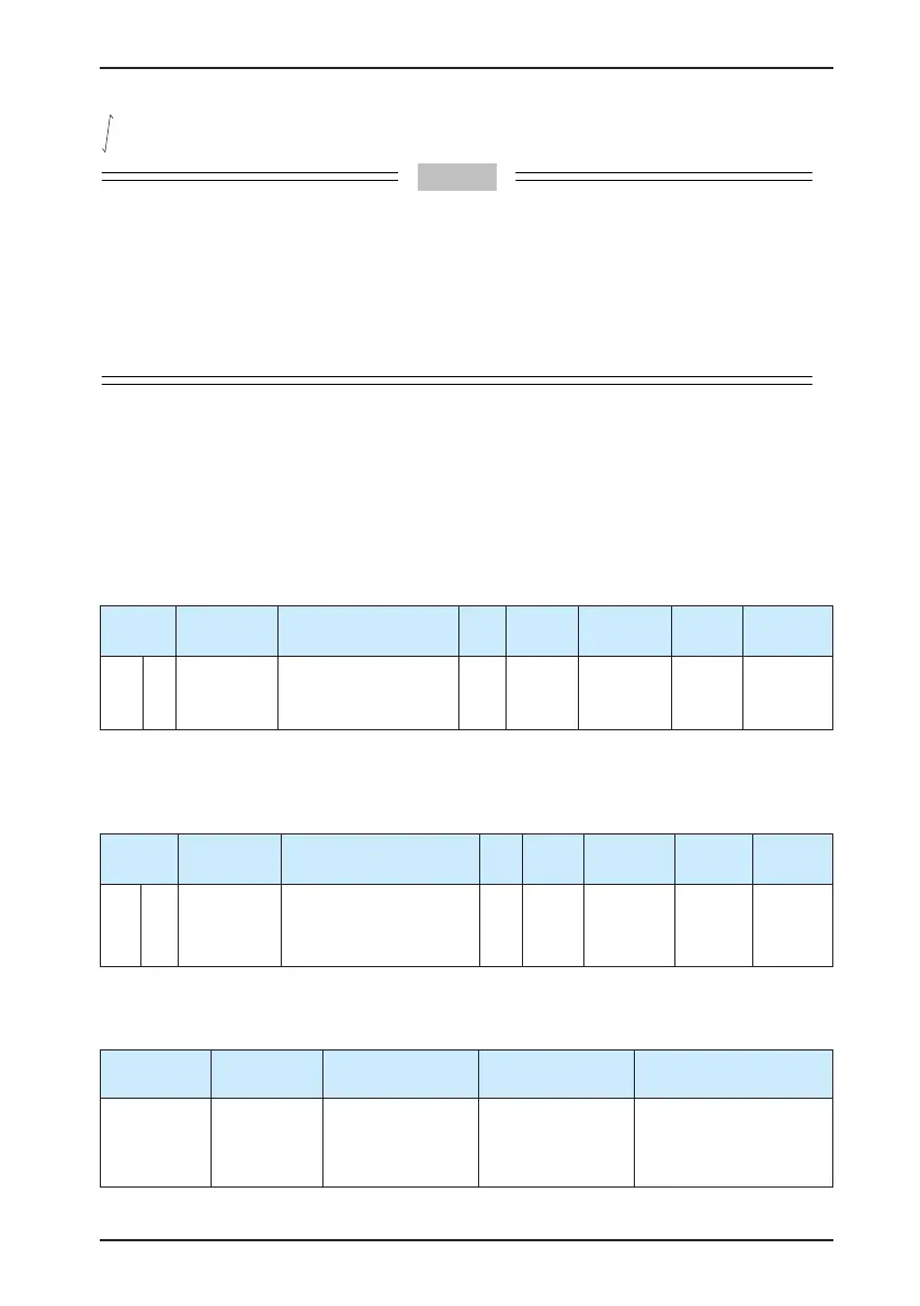
1. Position reference input setting
a. Position reference source
Use the default value 0 of H05-00, or set this parameter based on the actual situation.
Function
Code
Parameter
Name
Setting Range Unit Default
Effective
Time
Property
Control
Mode
H05 00
Position
reference
source
0: Pulse
1: Step setting
2: Multi-position setting
- 0 Immediate At stop P
b. Pulse reference input terminal selection
Specify whether the reference pulse source is high-speed pulse input or low-speed pulse input
by setting the function code H05-01.
Function
Code
Parameter
Name
Setting Range Unit Default
Effective
Time
Property
Control
Mode
H05 01
Pulse
reference
input
terminal
0: Low-speed pulse input
1: High-speed pulse input
- 0
Power-on
again
At stop P
c. Position reference direction setting
Set the function FunIN.27 to switch over the position reference direction by a DI.
Function No.
Function
Name
Description Setting Remarks
FunIN.27 POSDirSel
Position reference
direction
Valid: Forward
direction
Invalid: Reverse
direction
It is recommended
that the logic of the
corresponding terminal
be set to level valid.

 Loading...
