IS620P User Manual Chapter 4 Running and Commissioning
- 91 -
4.3 Use of the Torque Control Mode
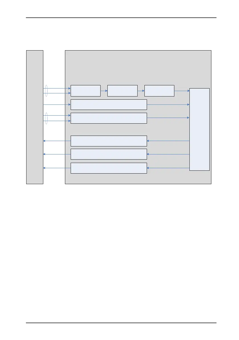
Figure 4-12 Diagram of the torque control mode
Reference input
setting
Speed
regulator
Host
controller
Torque
reference
input
H07-00 Main torque
reference A source
H07-01 Auxiliary torque
reference B source
H07-02 Torque
reference source
H07-05 Torque
reference filter time
constant 1
Reference filter Reference limit
Reference direction selection
SPDDirSel
input
Torque limit
Servo drive
H07-07 Torque limit source
H07-08 T-LMT selection
H07-09 Internal forward torque limit
H07-10 Internal reverse torque limit
H07-11 External forward torque limit
H07-12 External reverse torque limit
H07-17 Speed limit source
H07-18 V-LMT selection
H07-19 Forward speed limit/
Speed limit 1 in torque control
H07-
20 Reverse speed limit/
Speed limit 2 in torque control
Speed limit function
V-LT output
Torque limit output
C-LT output
Toq-Reach
output
Torque reached output
H07-21 Base value for torque reached
H07-22 Threshold of torque reached valid
H07-23 Threshold of torque reached invalid
External AI
speed limit
input
The main use procedure of the torque control mode is as follows:
1. Connect the power cables of the main circuit and control circuit of the servo drive, motor
power cables, and encoder cables correctly. After power-on, the keypad of the servo drive
displays "rdy", indicating that the wiring is correct.
2. Perform trial jog running by pressing keys and ensure that the motor can run properly.
3. Connect the required DI/DO signals and analog speed references of terminal CN1
according to Figure 4-13.
4. Perform the setting related to the torque control mode.
5. Set a low speed limit, send a forward or reverse torque reference, and check whether the
rotating direction of the motor is correct and whether the torque is correctly limited. If yes,
the servo system can be used properly.
 Loading...

