11
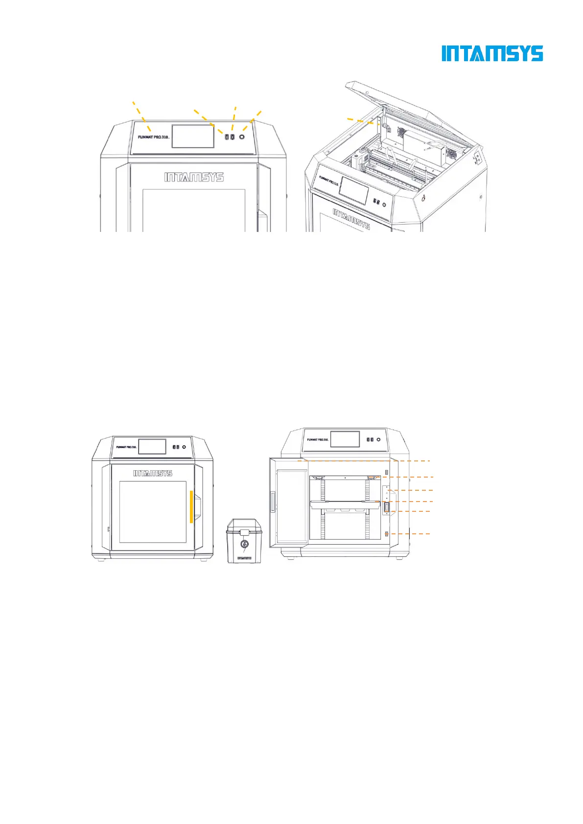
Fig. 3.3 Schematic Diagram of Top Door Opening Fig. 3.4 Schematic Diagram of User Operation Area
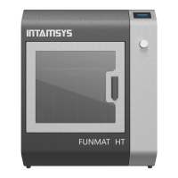
3.3 Printing Chamber Components
The front door can be pulled open from the right side by the release of the electromagnetic suction
of the front door through screen operation, and then it can be seen that the printing chamber contains
front door, hot bed, double extruder assembly, electromagnetic suction, magnetic suction and door
sensor.
When the printing chamber is heated, its stainless steel build plate and side plates are hot. Please do
not touch them to avoid scalding.
The four leveling knobs under the hot bed are used to manually level the printing platform.
Fig. 3.5 Schematic Diagram of Front Door Opening Mode Fig.3.6 Printing Chamber
3.4 Independent Filament Box
The printer is supplied with an external INTAMBox Sealed Drying Filament box that can hold up
to two rolls of 1 kg material. Seal rings and buckles are provided around the filament box to ensure
its sealing performance. The filament box is supplied with a drying box filled with 4A molecular
sieve desiccant, which can ensure the low humidity environment inside the filament box. The upper
cover of the filament box is equipped with a charging tray tension device to ensure that the printing
wire rod will not be loosen during printing and that the wire coil will not topple when the wire rod