13
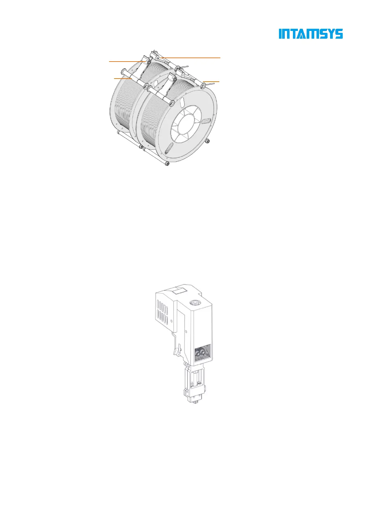
Fig. 3.9 Working Diagram of Tension Device
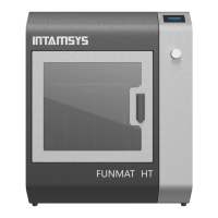
3.5 Print head Assembly
The print head assembly is used to melt the wire and form a desired model on the printing build
plate in combination with the movement of X-axis, Y-axis and Z-axis. A machine contains two
separate print heads, generally the left extruder for printing model material and the right extruder
for printing support material. Generally, there's only one extruder performing printing at the same
time point, while the other extruder stands by at the end of X-axis. When copying or mirror printing
is carried out, the two extruders move simultaneously.
Refer to Chapter 5 for loading and unloading of materials.
Fig. 3.10 Extruder Assembly
3.5 X/Y Axis Components
X-axis and Y-axis components drive the double-extruder to move within the XY plane according to
commands.
X-axis and Y-axis are driven by the synchronous belts, whose tension has been properly adjusted at