iPECS UCP
Hardware Description and Installation Manual Issue 1.3
98
Wiring Connectors
Before wiring any of the Modules, first connect the “ ” screw on the back of the Module to a
known ground, refer to 6.1.4. If installed in a cabinet assure the cabinet is grounded.
On the front of the WTIM is the RJ–45 type “LAN” connector. This connector should be wired to
the appropriate LAN points as discussed in 6.1.6 and 6.1.7.
Wire “LAN” to a 10/100 Base-T switch, an ES8GP/ES8G can be used to connect to the
LAN.
Tag or number wiring for maintenance.
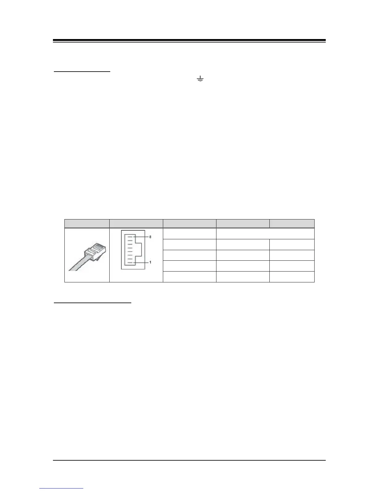
The RJ-45 connectors on the rear of the WTIM are used to connect to the Base Stations. This
wiring is detailed in the System DECT Installation Manual. The pin assignments given in Table
6.16-3 below are provided for reference only.
Table 6.16-3 WTIM4/8 Pin assignments
Multiple WTIM connection
When multiple WTIMs are installed and handover between Base Stations (GDC-600BEs) is
required, the WTIMs must be interconnected. Up to three (3) WTIMs may be interconnected to
allow handover between the connected Base Stations. Wiring for this connection is shown in
Figure 6.166-1 below. The WTIM interconnection is a separate connection not provided by the
back panel, thus, even when the WTIMs are installed in a cabinet the interconnection of the
WTIMs is required.
On the front of the WTIM are the RJ–45 type Sync Cable In and Sync Cable Out connectors.
These connectors should be wired to the appropriate Sync Cable In/Out connector of the next
WTIM as discussed above.
Wire “Sync Cable Out” directly to the “Sync Cable In” of the next WTIM as shown in
Figure 6.166-1 below.
Tag or number wiring for maintenance.
Note that power must be removed prior to connecting the Sync Cable between WTIMs.
 Loading...


