iPECS UCP
Hardware Description and Installation Manual Issue 1.3
16
In addition, the UCP100 server module incorporates two built-in FXS ports. An outside Line
option unit with four (4) analog CO Lines, two (2) BRI Lines, or four (4) BRI Lines may be installed.
The BRI lines support the ETSI standards for ISDN. Note the option unit will reduce the number
of available VoIP DSP channels. The 4-CO Line and 2-BRI Line option unit reduce the available
VoIP DSP channels by two and the 4-BRI Line option unit reduces the VoIP channels by four.
The UCP100 automatically connects the first CO Line to the first SLT port should power to the
system fail. The UCP 600 and 2400 include four (4) Power Fail Transfer circuits that can be
wired to desired CO Lines and SLT ports for connection should system power fail.
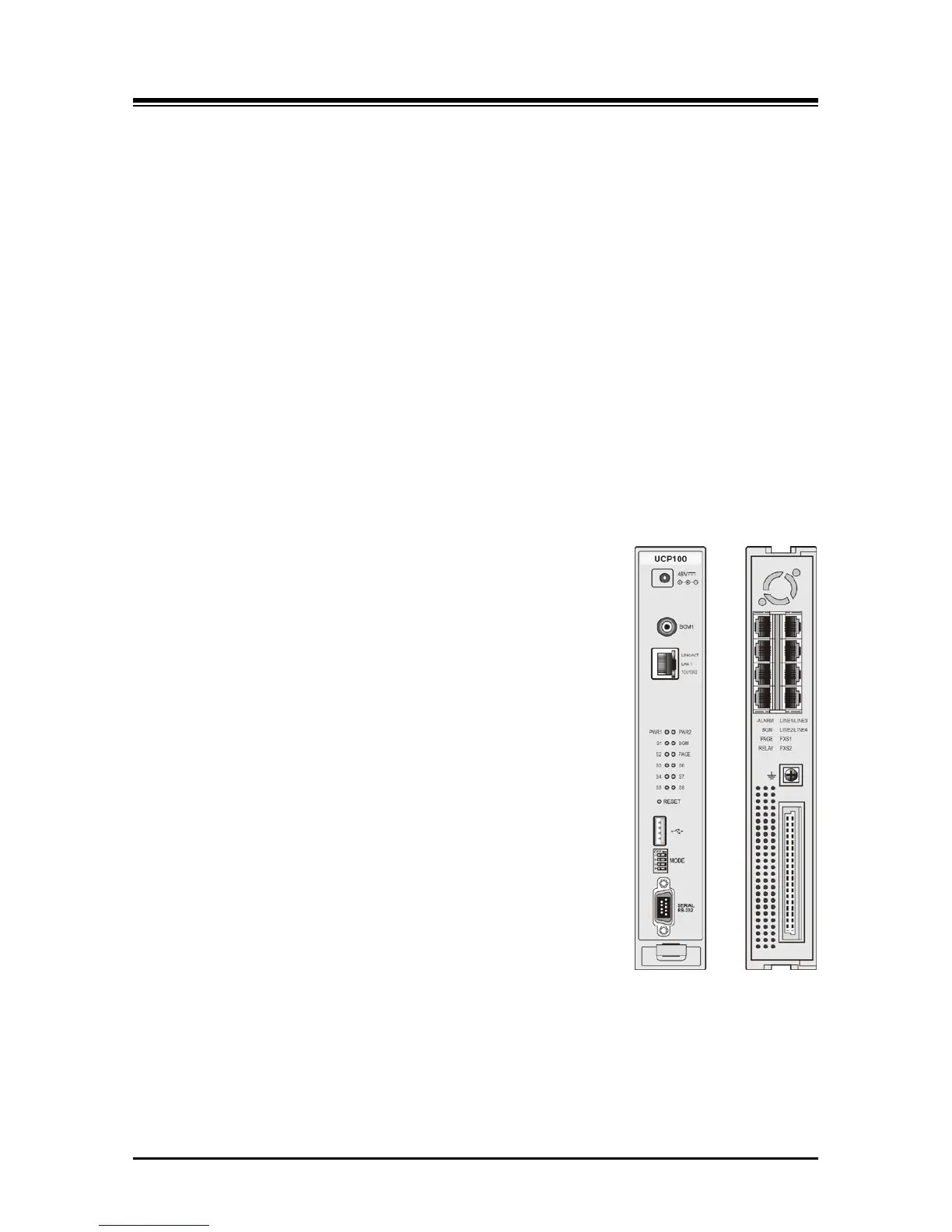
As shown in Figure 3.1.1-1, the UCP100 front panel includes:
Power jack for the AC/DC adapter; see 3.1.15 AD/DC adapter –G-
RCA jack for one music (audio) source -BGM1-
One (1) “LAN1” RJ-45 Female LAN connector with Speed and Link/Activity LEDs
Two (2) green power status LEDs
PWR1 - + 5 VDC
PWR2 - + 3.3 VDC
Ten (10) blue LEDs display the operating status
Reset Switch
One (1) USB 3.0 host, SIO/USB Memory port,
Four (4)-position DIP-switch for mode selections
One (1) DB-9 RS-232 connector
On the rear panel, each UCP100 has:
Eight (8) RJ-45 female connectors for:
One (1) Alarm contact input
One (1) BGM/MOH external source input
One (1) External Page output
One (1) Control Relay contact output
Four (4) optional analog CO Line ports or 2 or 4 BRI (2B+D)
Lines
Two (2) FXS, one used as a Power Fail Transfer circuit
Ground Lug
Fifty (50)-pin back plane connector
Figure 3.1.1-1 UCP100 Front & Rear Panel