iPECS UCP
Hardware Description and Installation Manual Issue 1.3
17
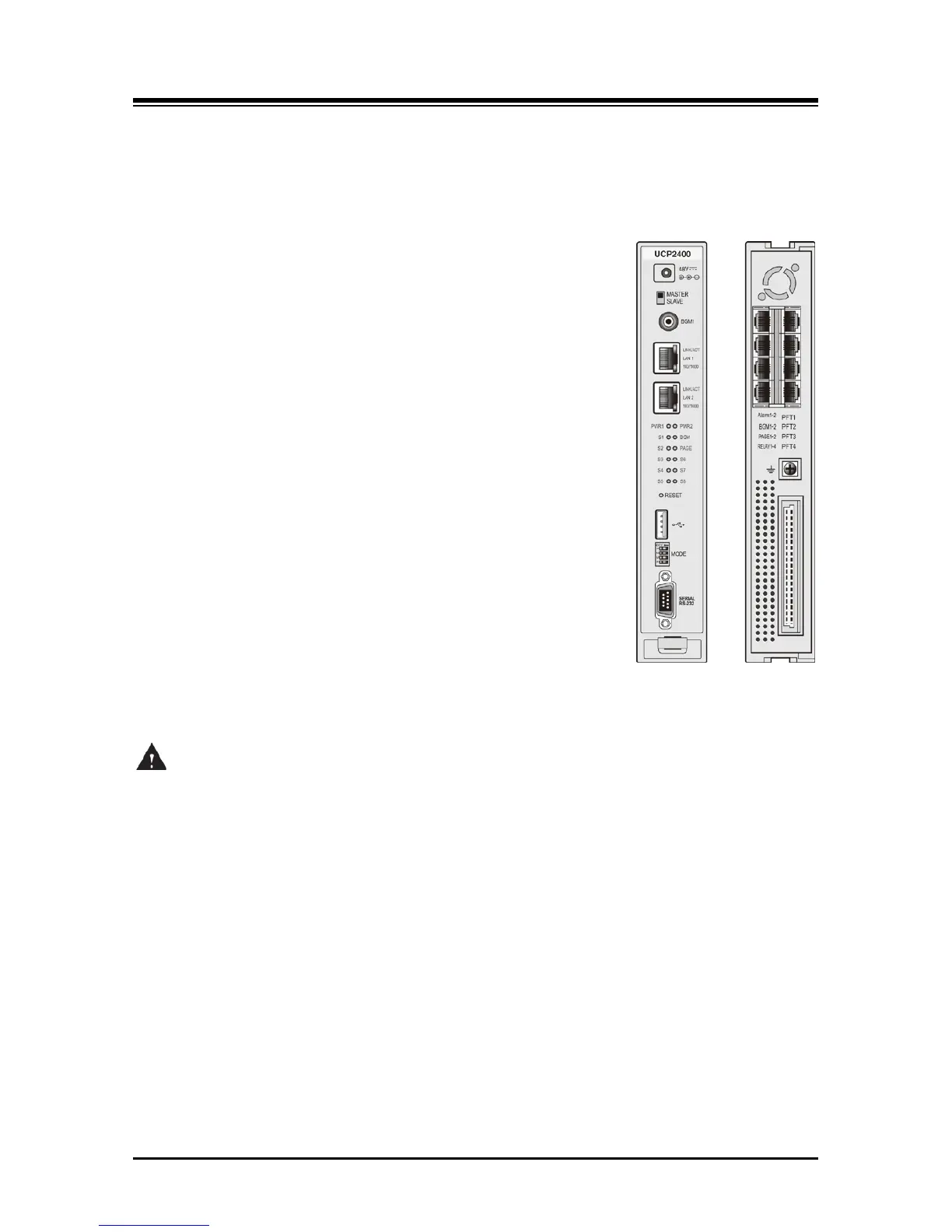
The UCP600 and UCP2400 module front panels are shown in Figure 3.1.1-2, and include;
Power jack for the AC/DC adapter; see 3.1.15 AD/DC adapter –G-
Master/Slave switch
RCA jack for one music (audio) source -BGM1-
Two (2) “LAN1” & “LAN2” RJ-45 Female LAN connectors with
Speed and Link/Activity LEDs
Two (2) green power status LEDs
PWR1 - + 5 VDC
PWR2 - + 3.3 VDC
Ten (10) blue LEDs display the operating status
Reset Switch
One (1) USB 3.0 host, SIO/USB memory port
Four (4)-position DIP-switch for mode selections
One (1) DB-9 RS-232 connector
On the rear panel, each UCP100 has:
Eight (8) RJ-45 female connectors; for Alarm, BGM and
Control Relay inputs, External Page outputs and Power Fail
Transfer circuits
Ground Lug
Fifty (50)-pin back plane connector
Figure 3.1.1-2 UCP600/2400 Front & Rear Panel
CAUTION
The USB port of the UCP module is designed for SIO and USB memory; the USB port does not
provide power to connected devices.