iPECS UCP
Hardware Description and Installation Manual Issue 1.3
56
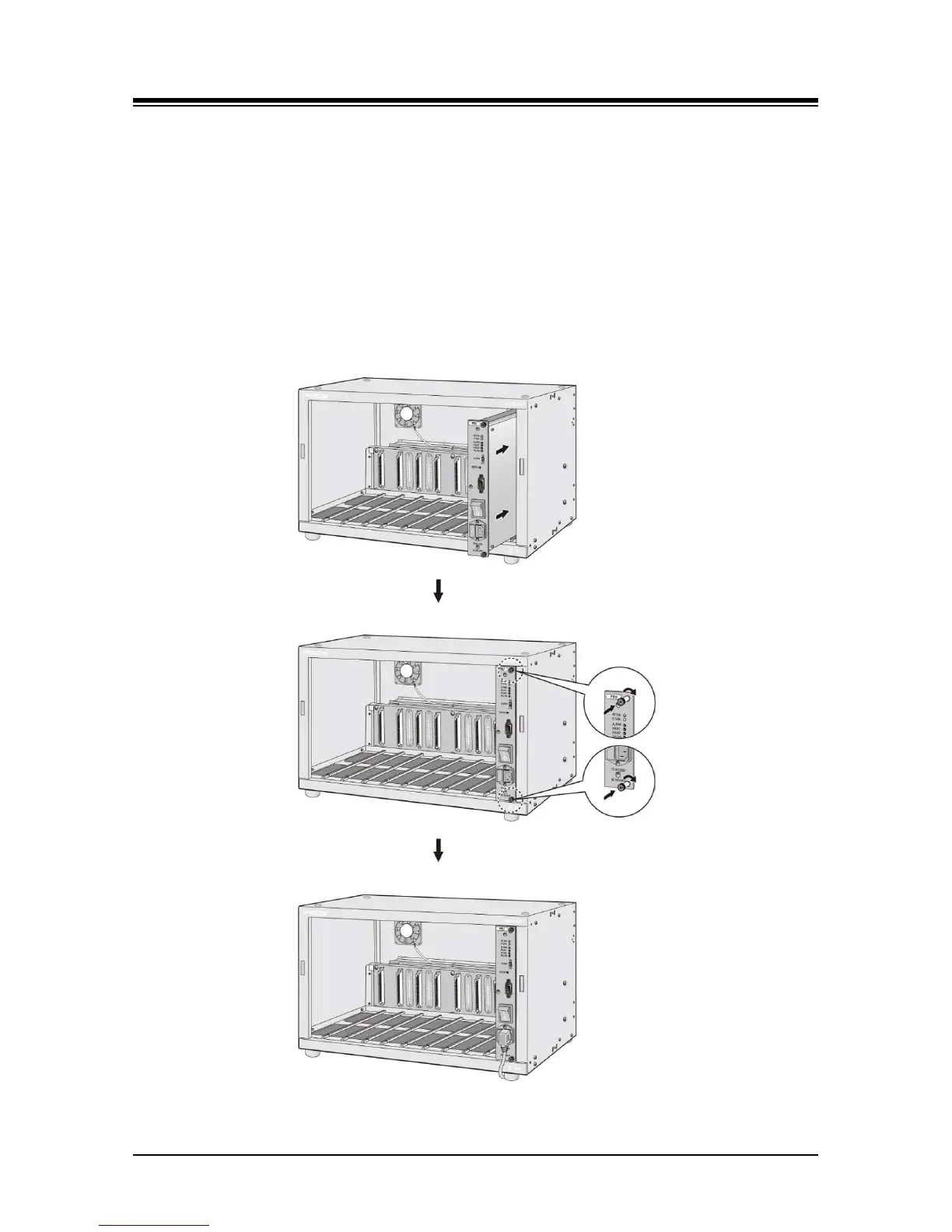
The main PSU is installed as described below and shown in Figure 5.3-1.
1. Slide the PSU into slot 10 of cabinet t to engage the back-panel connector fully.
2. Fasten the PSU by tightening the upper and lower thumbscrews on the front of PSU.
3. Plug the power cord into AC power input on the front of PSU.
4. To activate monitoring of the PSU and cabinet fans, connect the supplied serial cable
from the DB9 connector of the PSU to the gateway Module defined in the System Data
Cabinet Attributes. Refer to Figure 5.3-3. Note when a back-up PSU is installed, the
serial cable is connected to the back-up PSU only. Also, when employing a WTIM as the
notifying gateway Module, Dipswitch 3 of the WTIM, the Serial Mode switch, must be set
to OFF, the Main CPU Serial mode.
Figure 5.3-1 Main PSU Installation