Section E - Hydraulics
Transmission Pumps
Pump/Engine Coupling
E - 70 E - 70
9803-9450-2
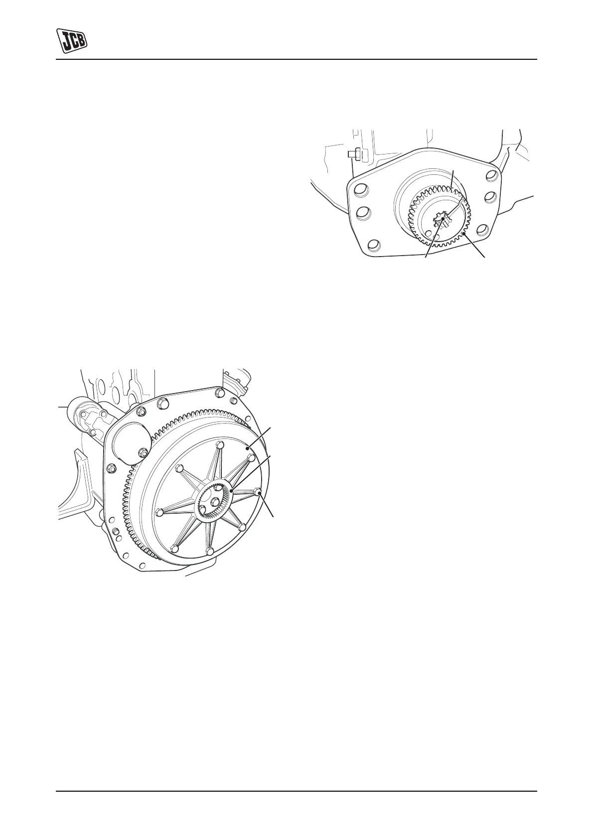
Pump/Engine Coupling
This is a gear type coupling comprising a drive plate A
bolted to the engine flywheel and a coupling B clamped to
the input shaft of the pump unit. Both are contained within
the engine bell housing (not shown) to which the pump unit
is bolted.
Drive plate A is secured to the flywheel with eight bolts C.
Coupling B is clamped onto the pump shaft spline with cap
screw D (not visible in illustration).
Ensure the drive plate is fitted with the flat face against the
flywheel and boss E facing outwards.
Before fitting coupling B to the pump input shaft ensure
that circlip F is fitted to the groove in the bore.
Coat threads of bolts C with JCB Threadlocker and Sealer
and torque tighten to 23 Nm (17 lbf ft, 2.3 kgf m).
Coat threads of capscrew D with JCB Retainer (High
Strength) and torque tighten to 49 Nm (36 lbf ft, 5 kgf m).
Fig 61.
Fig 62.
808240
808230
B
D
F