SECTION 4 - HYDRAULICS
4-2 – JLG Lift – 3121166
4.3 CYLINDER CHECKING PROCEDURE
NOTE: Cylinder check must be performed anytime a system
component is replaced or when improper system
operation is suspected.
Cylinders Without Counterbalance Valves
and Steer Cylinder
1. Using all applicable safety precautions, activate
pump motor and fully extend cylinder to be
checked.
2. Carefully disconnect hydraulic hoses from retract
port of cylinder. There will be some initial weeping of
hydraulic fluid which can be caught in a suitable
container. After the initial discharge, there should be
no further drainage from the retract port.
3. Activate pump motor and extend cylinder.
4. If cylinder retract port leakage is less than 6-8 drops
per minute, carefully reconnect hose to port and
retract cylinder. If leakage continues at a rate of 6-8
drops per minute or more, cylinder repair must be
made.
5. With cylinder fully retracted, shut down machine
power and carefully disconnect hydraulic hose from
cylinder extend port.
6. Activate pump motor and retract cylinder. Check
extend port for leakage.
7. If extend port leakage is less than 6-8 drops per
minute, carefully reconnect hose to extend port,
than activate cylinder through one complete cycle
and check for leaks. If leakage continues at a rate of
6-8 drops per minute or more, cylinder repairs must
be made.
4.4 LIFT PRESSURE SETTING PROCEDURE
1. Place 120% of the rated load of the machine on the
platform.
2. Increase lift pressure to raise the platform and set
the safety prop.
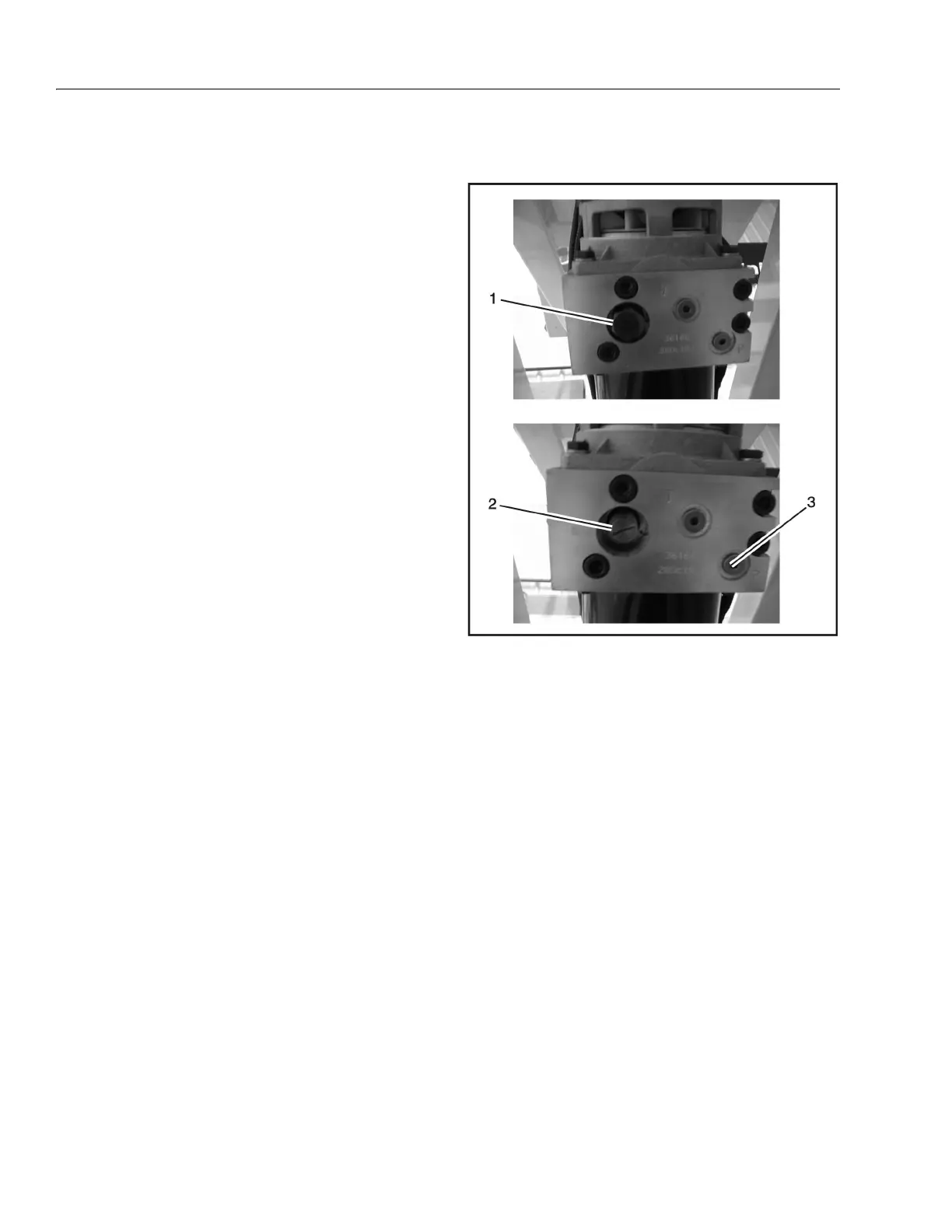
3. Locate the Large Nut (1) on the underside of the
valve block.
4. Using a 7/8 in. wrench, remove the large nut (1).
This will expose the Pressure Setting Screw (2).
5. Remove plug from P port (3) and install a pressure
gauge.
6. Raise the platform and take a pressure reading.
7. Adjust the Pressure Setting Screw to reach the
proper lift pressure per model as listed in Table 4-1.
Figure 4-1. Lift Pressure Setting
1. Large Nut
2. Pressure Setting Screw
3. P port