SECTION 3 - CHASSIS & SCISSOR ARMS
3121166 – JLG Lift – 3-35
8. Remove manual release screws from brake assem-
bly. Apply new Gasket (12) and affix brake cover to
motor using the 2 manual release screws.
9. Attach terminal cover to the commutator end head
using two terminal cover screws.
10. Slide the strain relief of the wire harness into the slot
of the terminal cover. Align cover plate with groove in
frame and field and affix using two cover plate
screws.
Drive Motor Servicing Guidelines
Because the operating environment of industrial equip-
ment varies widely, the following are suggested for peri-
odic maintenance inspection intervals.
• Normal Service – Perform routine inspection (outlined
in the Drive Motor Inspection and Service portion of
this section) every 1,000 hours of drive time.
• Severe Service – Perform routine inspection every 500
hours of drive time. Severe service environments are
listed below:
a. Dusty or dirty locations like cement plants, lum-
ber and flour mills, coal mining, stone quarries,
etc.
b. High temperature areas like steel mills, found-
ries, etc.
c. Environments with sudden temperature change,
such as in refrigeration plant, etc.
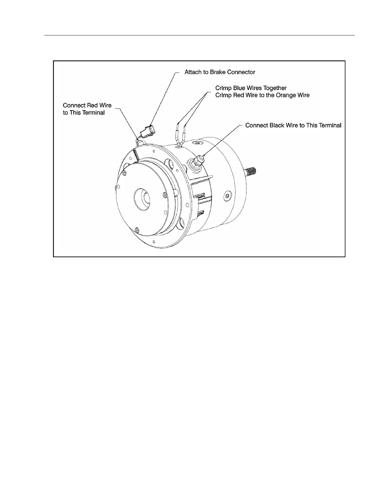
Figure 3-31. Wire Harness Connections