SECTION 6 - DIAGNOSTIC TROUBLE CODES
3121166 – JLG Lift – 6-9
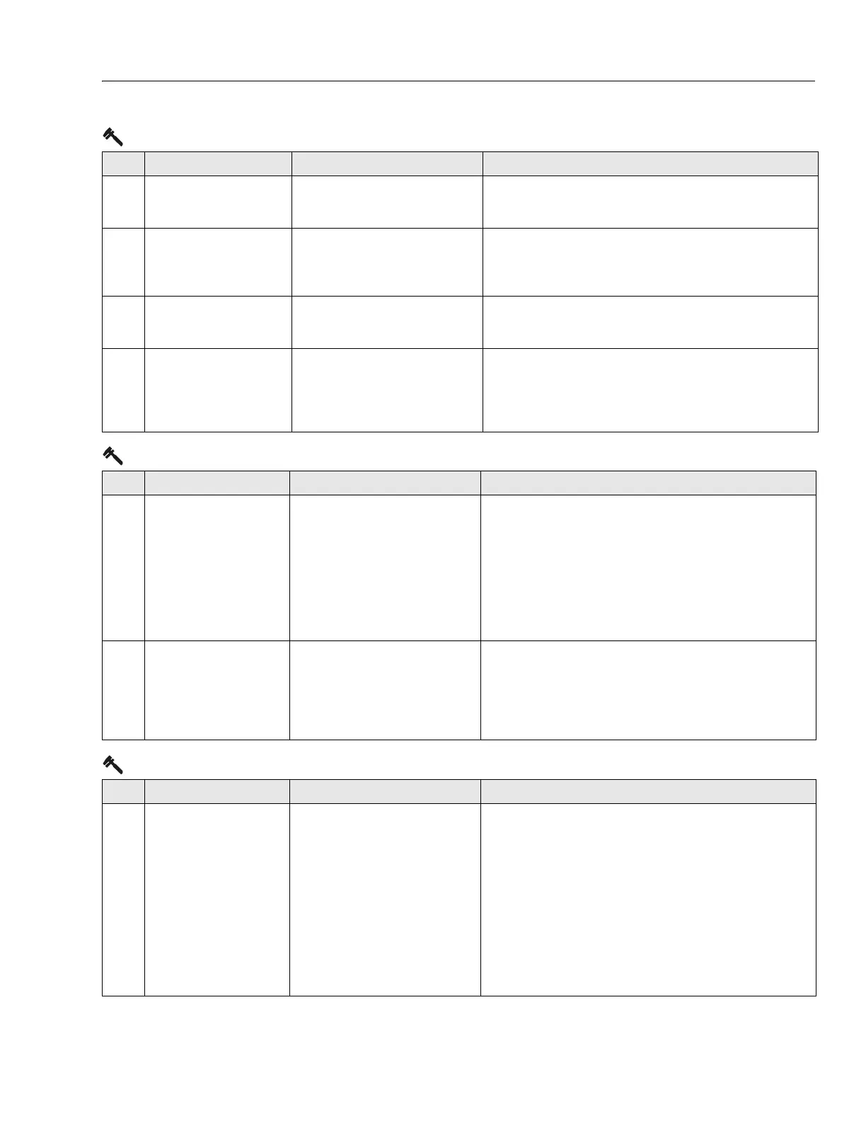
259 MODEL CHANGED -
HYDRAULICS SUSPENDED -
CYCLE EMS
The model selection has been changed. • Check ANALYZER -> MACHINE SETUP -> MODEL NUMBER.
• Replace ground board.
2510 DRIVE PREVENTED -
BRAKES NOT RELEASING
While driving on a level surface, armature
current was > 150A for five seconds.
Brakes assumed to not be releasing prop-
erly.
• Ensure vehicle is not stuck on something preventing movement.
• Check / repair drive motor wiring, brakes or mechanical issues.
2511 ELEV ANGLE SENSOR
FAULTY - NOT MOUNTED
The input voltage from the elevation
angle sensor indicates the elevation
angle sensor is not mounted.
• Check that the elevation angle sensor is securely mounted.
• Check that the elevation angle sensor mechanisms are intact.
• Replace elevation angle sensor.
2512 ELEV ANGLE SENSOR NOT
DETECTING CHANGE
The input voltage from the elevation
angle sensor did not change while vehicle
was lifting up.
• Check that the elevation angle sensor is securely mounted.
• Check elevation angle sensor is not jammed or obstructed.
• If there are any other elevation angle sensor, joystick, or lift up
faults, troubleshoot them before continuing.
• Replace elevation angle sensor.
3-1 Line Contactor Open Circuit
DTC FAULT MESSAGE DESCRIPTION CHECK
311 OPEN CIRCUIT LINE CON-
TACTOR
The power modules line contactor did not
close when energized. Drive, steer and lift
up prevented.
• Check contactor main contact wiring to battery (+) terminal and
power controller terminal B+.
• Contactor solenoid resistance should measure about 52 Ohms.
• Check contactor solenoid wiring to power module 12 position
connector terminal 8 and ground board terminal J1-19.
• Check that power module 12 position connector terminal 8 goes
from 24V to near 0V while contactor should be closing. If this
happens replace contactor.
• Replace the line contactor.
312 CONTACTOR DRIVER PER-
MANENTLY OFF
The power modules line contactor drive
circuitry failed to energize when
requested. Drive, steer and lift up pre-
vented.
• Check continuity between contactor connector pin 1 and ground
board socket J1-19.
• Contactor solenoid resistance should measure about 52 Ohms.
• Check continuity between contactor connector pin 2 and power
module connector socket 8.
• Replace power module.
3-2 Line Contactor Short Circuit
DTC FAULT MESSAGE DESCRIPTION CHECK
321 LINE CONTACTOR MIS-
WIRED ON OR WELDED
Battery voltage was present at the power
module B+ terminal at power up. Drive,
steer and lift up prevented.
• Check wiring of contactor.
• Check resistance between the studs of the contactor while dis-
connected from the machine.
• Check contactor main contact wiring to battery (+) terminal and
power module terminal B+.
• Check continuity between contactor connector pin 1 and ground
board socket J1-19.
• Check continuity between contactor connector pin 2 and power
module 12 position connector terminal 8.
• Measure voltage between power model B+ and B- terminals. If
24V is present, replace line contactor.
• Replace power module.
2-5 Function Prevented
DTC FAULT MESSAGE DESCRIPTION CHECK