SECTION 3 - CHASSIS & SCISSOR ARMS
3-62 – JLG Lift – 3121166
3.16 ARMS AND PLATFORM POSITIONING
AND SUPPORT
PLATFORM IS HEAVY AND PRESENTS A CRUSHING HAZARD.
TAKE GREAT CARE WHEN REMOVING PLATFORM OR SCISSOR
ARM ASSEMBLY
The arm stack can be supported by using an overhead
crane,(See Figure 3-47.). If an overhead crane is not avail-
able the stack may also be lifted by using a forktruck
using the following instructions:
1. With the forks on the forktruck slid close together,
enter from the front of the machine and place the
forks on the cross tube of the second arm weldment
below the platform.
2. Slowly lift the arm stack with the forktruck while the
manual descent valve is being engaged (this allows
the oil to drain back into the tank).
3. Place machine on safety prop and leave the fork-
truck in place.
4. At this point the lift cylinder removal may begin.
(Refer to Section 4.6, Lift Cylinder Removal)
If removal of the platform becomes necessary use the
above procedure to stabilize the platform for pin and plat-
form removal.
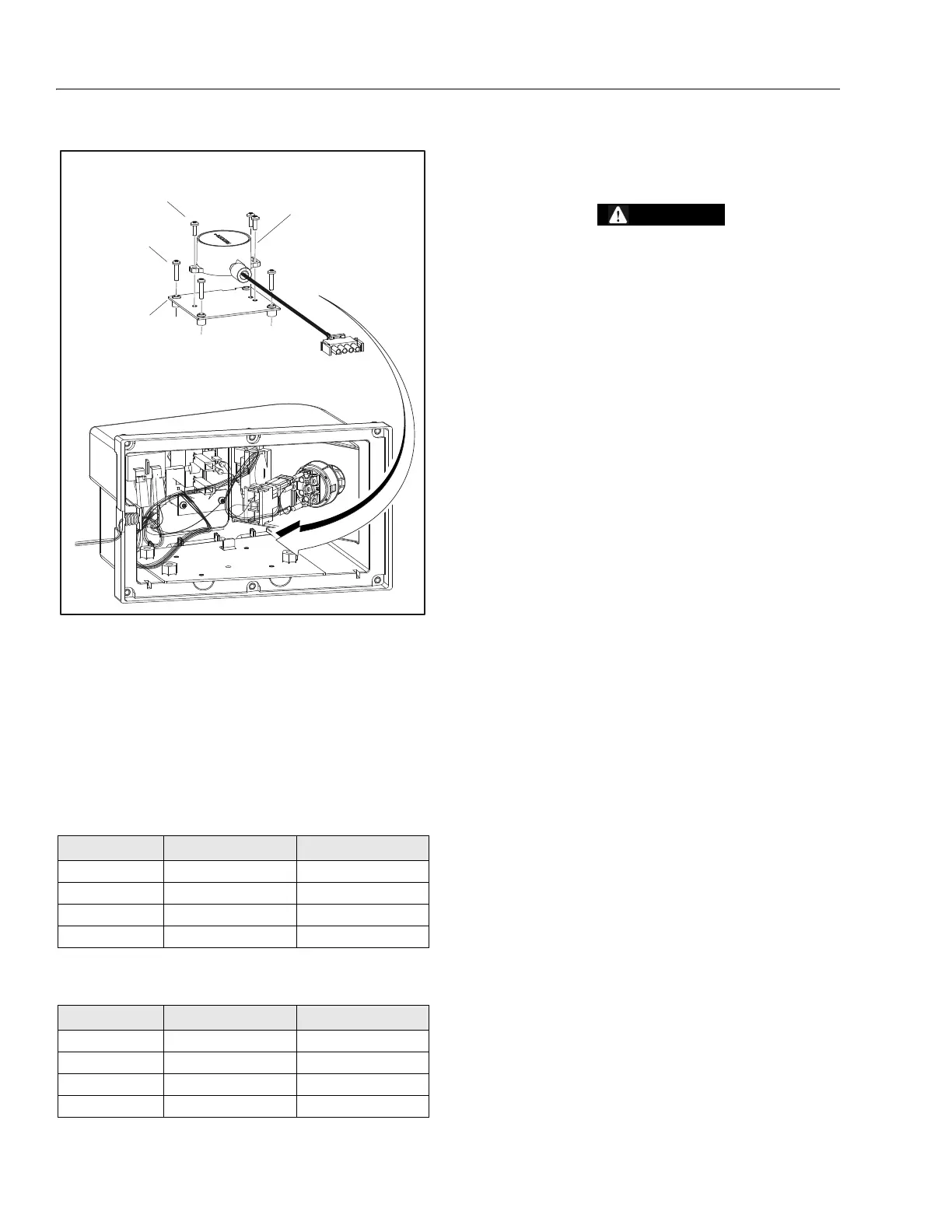
Table 3-7. Tilt Sensor Harness for 4000021
Wire Color Function Connector Pin
Red VCC 1
Green PWMX 2
White PWMY 3
Black Ground 4
Table 3-8. Tilt Sensor Harness for 1001114936
Wire Color Function Connector Pin
Red VCC 1
White CANH 2
Green CANL 3
Black Ground 4
1. Tilt Sensor (JLG P/N 4000021 or
1001114936)
2. Sensor Mount
3. Screw, 3.5 x 0.6 x 16 LG
4. Screw, 3.5 x 0.6 x 10 LG
Figure 3-46. Tilt Sensor Removal