SECTION 3 - CHASSIS & SCISSOR ARMS
3121166 – JLG Lift – 3-29
NOTE: A well-planned maintenance program will save many
hours of future down time and expense on a piece of
equipment. Periodic maintenance consisting of
inspections of motors, batteries and wiring circuitry
is recommend.
EYE PROTECTION SHOULD BE WORN DURING ANY MAINTE-
NANCE OPERATION.
Disassembly
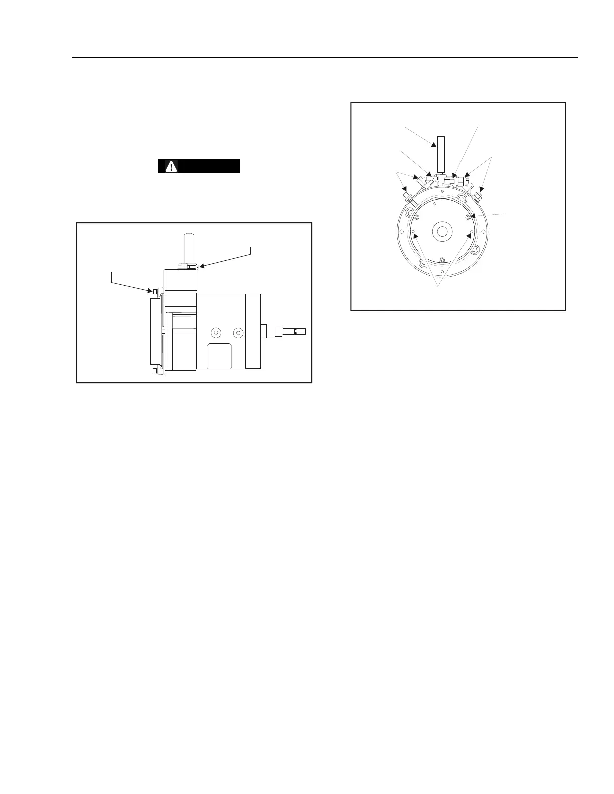
1. Remove the 2 (#8-32UNC x.50 in long) screws hold-
ing the cover plate in place and remove the cover
plate from the motor
.
2. Remove the 2 (M5 x 0.8 x 20mm long) screws hold-
ing the cover (15) in place and set aside. These
screws are needed later to manually release the
brake. Slide the strain relief bushing (14) and wire
harness out of the cover and remove the cover from
the motor. Remove strain relief bushing from wire
harness and set aside.
3. Discard the O-ring (13) located inside the cover.
4. Remove the wire harness (8) from the motor by dis-
connecting the field connection and brake connec-
tion. Install the 2 cover mounting screws into the
threaded holes in the brake assembly and tighten to
manually release the brake. See Figure 2 below or
image in the “Manual Disengage Procedure” on
page 8 of the gearbox section of this manual.
5. Remove the 3 screws holding the brake assembly
(11) to the motor. Carefully remove the brake assem-
bly and friction disk (10) from the motor by sliding it
off of the shaft.
6. Remove the screws holding the commutator end
head (9) in place and remove the commutator end
head from the frame and field assembly (1). The
armature (2) will be attached to the commutator end
head.
7. Pull back the brush springs (4) in the commutator
end head, pull the brush back and rest the springs
on the side of the brush. The brushes should move
freely within the holders.
8. Use an arbor press or a bearing puller to remove the
armature from the commutator end head assembly.
9. Remove the snap ring (6) and bearing (7) from the
commutator end head. Discard the bearing.
COVER PLATE
MOUNTING SCREWS
COVER MOUNTING
SCREWS
WIRE HARNESS
BRAKE CONNECTOR
RED WIRES
THREADED HOLES IN
BRAKE ASSEMBLY
BRAKE ASSEMBLY
MOUNTING SCREWS
BLACK WIRES
FIELD CONNECTION