SECTION 4 - HYDRAULICS
3121166 – JLG Lift – 4-13
17. If applicable, inspect piston rings for cracks or other
damage. Replace as necessary.
Assembly
NOTE: Prior to cylinder assembly, ensure that the proper
cylinder seal kit is used. See your JLG Parts Manual
(3121167).
Apply a light film of hydraulic oil to all components prior to
assembly.
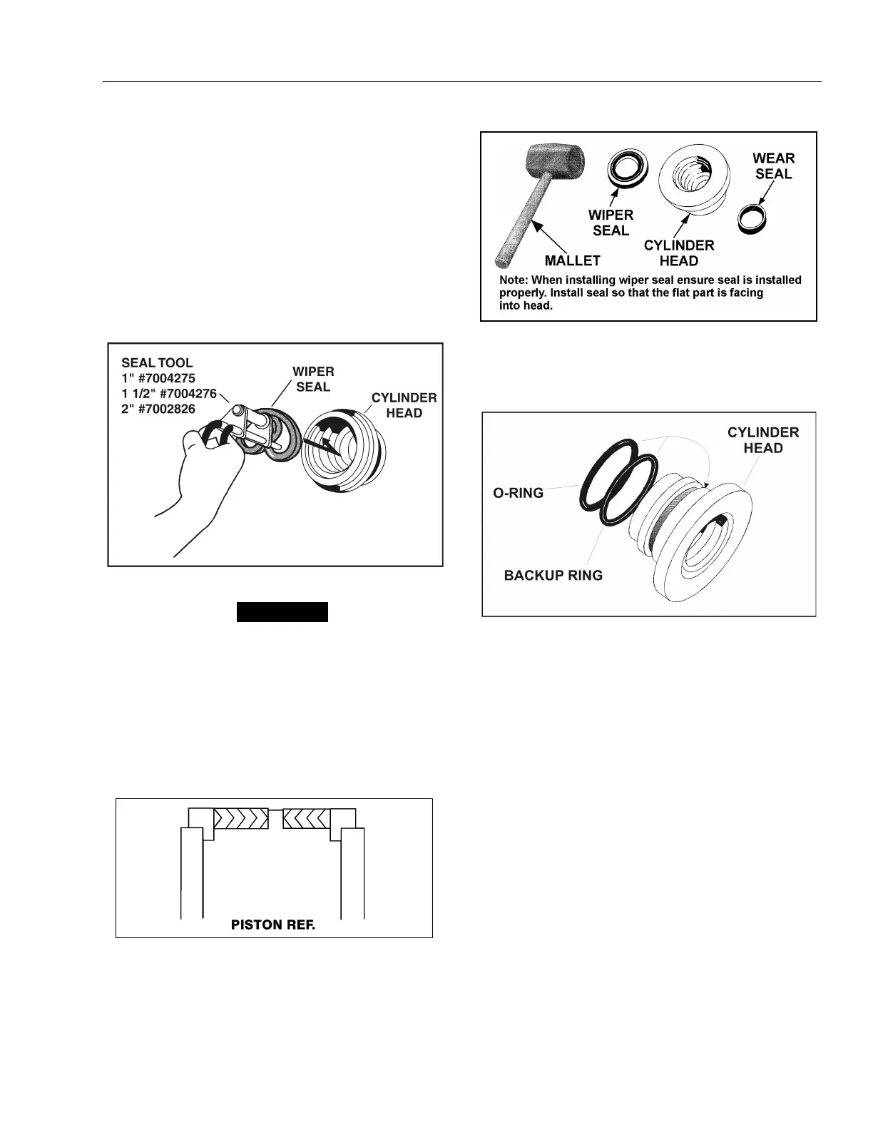
1. A special tool is used to install a new rod seal into
the applicable cylinder head gland groove.
WHEN INSTALLING ‘POLY-PAK’ PISTON SEALS, ENSURE SEALS
ARE INSTALLED PROPERLY. REFER TO WIPER SEAL INSTALLA-
TION FOR CORRECT SEAL ORIENTATION. IMPROPER SEAL
INSTALLATION COULD RESULT IN CYLINDER LEAKAGE AND
IMPROPER CYLINDER OPERATION.
2. Use a soft mallet to tap a new wiper seal into the
applicable cylinder head gland groove. Install a new
wear ring into the applicable cylinder head gland-
groove.
3. Place a new “O-ring and back-up seal in the applica-
ble outside diameter groove of the cylinder head.
4. Install washer ring onto rod, carefully install the head
gland on the rod, ensuring that the wiper and rod
seals are not damaged or dislodged. Push the head
along the rod to the rod end, as applicable.
5. Carefully slide the piston spacer on the rod.
NOTE: Upper telescope cylinder piston has an o-ring
installed inside the spacer.
6. If applicable, correctly place new o-ring in the inner
piston diameter groove. (The backup ring side fac-
ing the O-ring is grooved.)
7. If applicable, correctly place new seals and guide
lock rings in the outer piston diameter groove. (A
tube, with I.D. slightly larger than the O.D. of the pis-
ton is recommended to install the solid seal.)
NOTE: The backup rings for the solid seal have a radius on
one side. This side faces the solid seal.(See magni-
fied insert in Figure 4-9. The split of seals and
backup rings are to be positioned so as not to be in
alignment with each other.
Figure 4-6. Rod Seal Installation
Figure 4-7. Poly-Pak Piston Seal Installation
Figure 4-8. Wiper Seal Installation
Figure 4-9. Installation of Head Seal Kit