SECTION 4 - HYDRAULICS
4-14 – JLG Lift – 3121166
1. Using suitable protection, clamp the cylinder rod in
a vise or similar holding fixture as close to piston as
possible.
2. Carefully thread the piston on the cylinder rod hand
tight, ensuring that the o-ring and back-up rings are
not damaged or dislodged.
3. Thread the piston onto the rod until it abuts the
spacer end and install the tapered bushing.
NOTE: When installing the tapered bushing, piston and mat-
ing end of rod must be free of oil.
4. Assemble the tapered bushing loosely into the pis-
ton and insert JLG capscrews (not vendor cap-
screws) through the drilled holes in the bushing and
into the tapped holes in the piston.
5. Tighten the capscrews evenly and progressively in
rotation to the specified torque value.
6. After the screws have been torqued, tap the tapered
bushing with a hammer (16 to 24 oz.) and brass
shaft (approximately 3/4" in diameter) as follows;
a. Place the shaft against the cylinder rod and in
contact with the bushing in the spaces between
the capscrews.
b. Tap each space once; this means the tapered
bushing is tapped 3 times as there are 3 spaces
between the capscrews.
7. Retorque the capscrews evenly and progressively in
rotation to the specified torque value.
8. Remove the cylinder rod from the holding fixture.
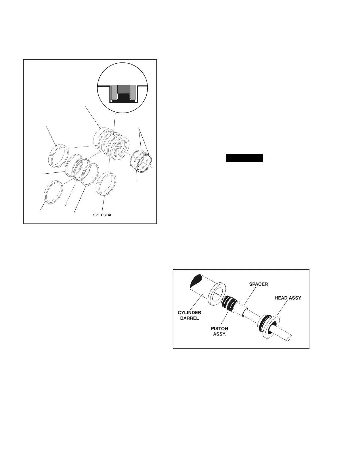
9. Place new guide locks and seals in the applicable
outside diameter grooves of the cylinder piston.
(See Figure 4-10.)
10. Position the cylinder barrel in a suitable holding fix-
ture.
EXTREME CARE SHOULD BE TAKEN WHEN INSTALLING THE
CYLINDER ROD, HEAD, AND PISTON. AVOID PULLING THE ROD
OFF-CENTER, WHICH COULD CAUSE DAMAGE TO THE PISTON
AND CYLINDER BARREL SURFACES.
11. With the barrel clamped securely, and while ade-
quately supporting the rod, insert the piston end into
the barrel cylinder. Ensure that the piston loading o-
ring and seal ring are not damaged or dislodged.
12. Continue pushing the rod into the barrel until the cyl-
inder head gland can be inserted into the barrel cyl-
inder.
13. Secure the cylinder head gland using the washer
ring and socket head bolts.
14. After the cylinder has been reassembled, the rod
should be pushed all the way in (fully retracted) prior
to the reinstallation of any holding valve or valves.
15. If applicable, install the cartridge-type holding valve
and fittings in the rod port block, using new o-rings
as applicable. (See Table 4-3, Holding Valve Torque
Specifications).
BACKUP
RINGS
O-RING
PISTON
SPLIT SEAL
SEAL
SPLIT BACKUP RING
T - RING
SPLIT
BACKUP
RING
Figure 4-10. Piston Seal Kit Installation
Figure 4-11. Rod Assembly Installation