SECTION 3 - CHASSIS & SCISSOR ARMS
3-2 – JLG Lift – 3121166
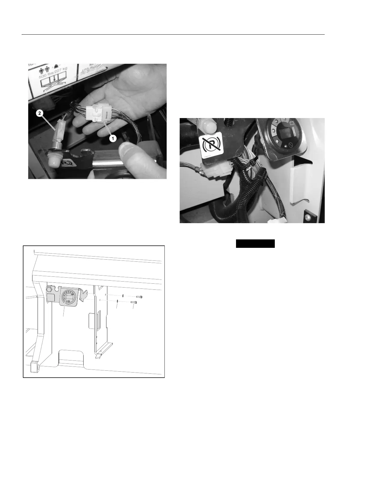
4. Connect the MDI harness to the Diagnostic Port.
5. Using a 5/32" allen wrench, mount the MDI and
Brake Release Bracket onto the wall of the battery
compartment. (appropriate mounting holes are pre-
existing) Apply Loctite #242 to the screws and
torque to 3.6 ft-lb (5 Nm). (Refer to Figure 3-2.)
5. Power machine and check to ensure LEDs on MDI
work. Check to ensure Brake Release Button works.
If the Software Version is not P1.13 or higher, "Error"
will display on the LCD. If a fault exists, the trouble
code will display on the LCD. (Refer to Section 6,
Diagnostic Trouble Codes)
6. Using zip ties, tie back cables and wires to prevent
damage to the cables and wires.
Removal:
ENSURE EMS BUTTONS ON THE CONTROL STATIONS ARE
PUSHED IN TO THE OFF POSITION BEFORE DISCONNECTING
THE MDI AND BRAKE RELEASE BRACKET.
1. Remove the two Screws (2) and Washers (3).
2. Disconnect Brake Release and MDI from the electri-
cal harnesses.
3. Remove Bracket.
1. MDI Connected
2. Brake Release Connected
Figure 3-2. MDI Installation/Removal
1. MDI & Brake Release Bracket
2. Screw, M5 x 16
3. Washer, 5mm