SECTION 3 - CHASSIS & SCISSOR ARMS
3121166 – JLG Lift – 3-7
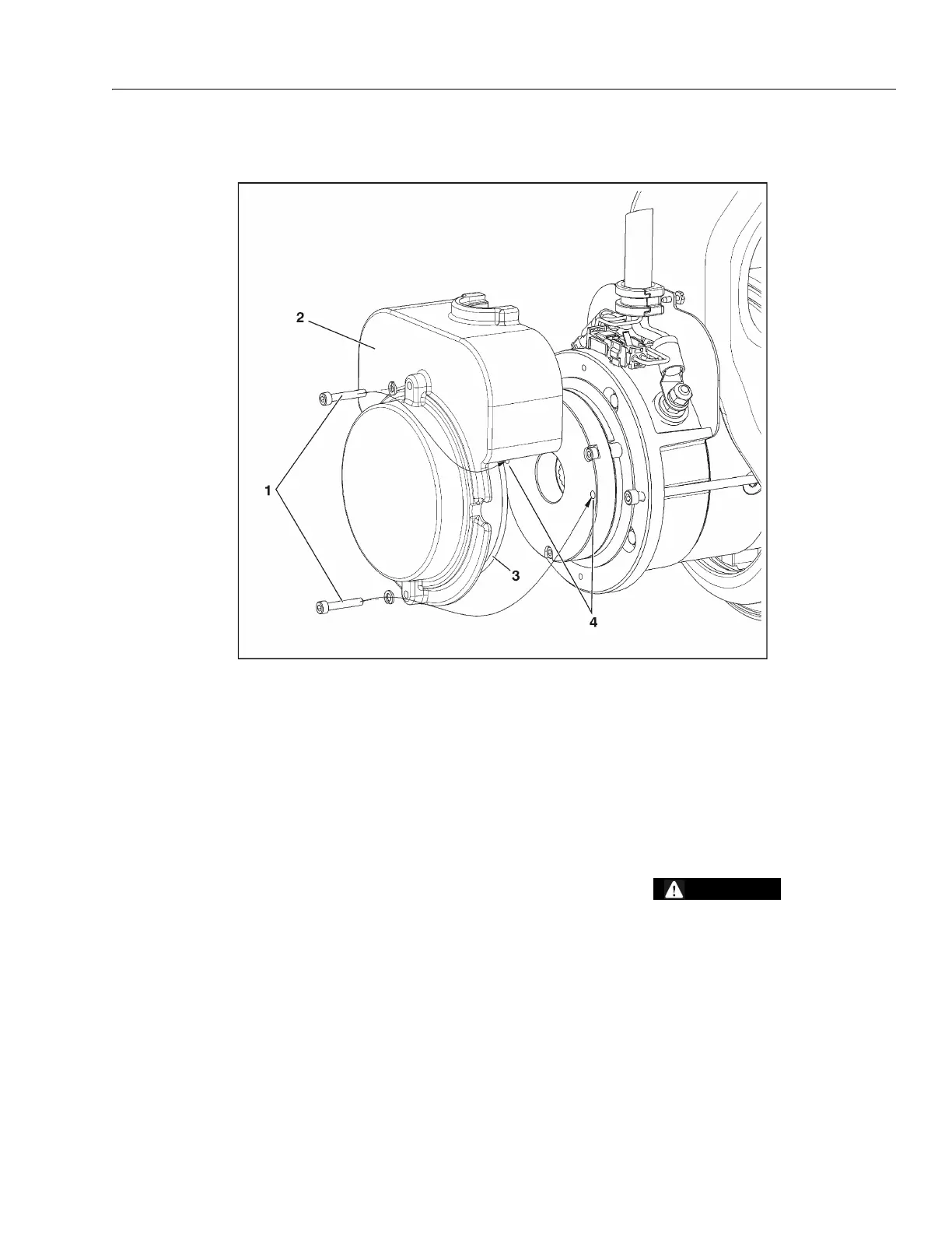
Manual Disengage Procedure
NOTE: Applies only to:
USA machines built S/N 0200152825 to S/N
020170585,
Belgium machines built S/N 1200008481 to S/N
1200015159.
1. Chock wheels or secure machine with tow vehicle.
2. Power machine in ground mode.
3. Remove the two cover bolts, cover, and cover o-ring
seal from the back of drive motor unit.
4. Insert the cover bolts into the two disengage holes in
the brake housing.
5. Tighten down the bolts and the brake on that drive
motor will disengage.
6. Repeat this procedure on opposite wheel drive. With
both drive motor brakes now disengaged, the
machine can be moved manually.
7. After towing is complete, chock wheels and remove
cover bolts from disengage holes.
8. Reinstall cover. Before installation, check the cover
o-ring seal for damage, replace if necessary.
AFTER THE MACHINE IS TOWED, THE DISENGAGE BOLTS MUST
BE REMOVED FROM THE BRAKE DISENGAGE HOLES. THE
BRAKES CANNOT BE ENGAGED WITH THE DISENGAGE BOLTS
IN THE BRAKE DISENGAGE HOLES. THIS WILL CAUSE THE
MACHINE TO ROLL WHEN PARKED ON AN INCLINE.
1. Brake Cover Bolts
2. Brake Cover
3. Cover O-ring Seal
4. Disengage Holes
Figure 3-6. Disengage Procedure