SECTION 6 - DIAGNOSTIC TROUBLE CODES
6-10 – JLG Lift – 3121166
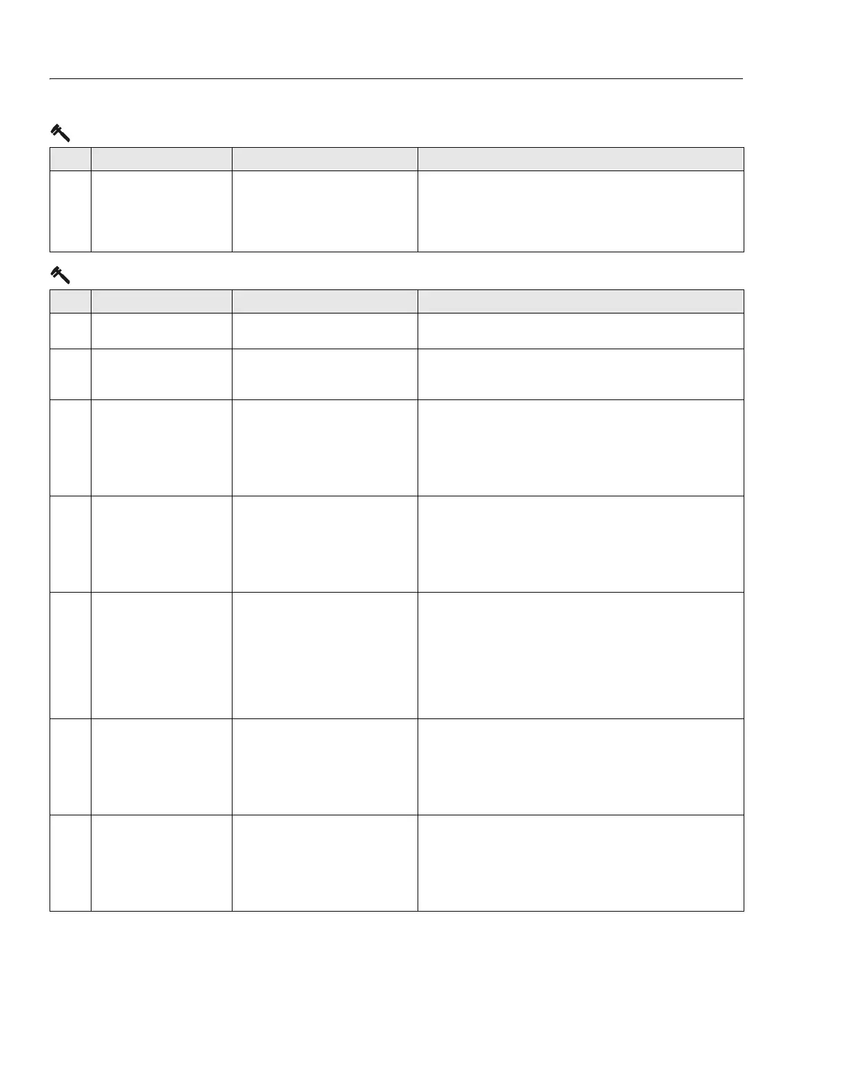
322 CONTACTOR DRIVER PER-
MANENTLY ON
The power modules line contactor drive
circuitry failed to de-energize when
requested. Drive, steer and lift up pre-
vented.
• Check continuity between contactor connector pin 1 and ground
board socket J1-19.
• Check continuity between contactor connector pin 2 and power
module 12 position connector terminal 8.
• Replace power module.
3-3 Ground Output Driver
DTC FAULT MESSAGE DESCRIPTION CHECK
331 BRAKE SHORT TO BATTERY The ground board detected voltage while
the brake solenoid was commanded off.
• Ensure ANALYZER -> MACHINE SETUP -> ELEV PROX is set to
NOT INSTALLED.
332 BRAKE OPEN CIRCUIT The ground board did not detect current
flow to the brake solenoid during normal
operation.
• Ensure ANALYZER -> MACHINE SETUP -> ELEV PROX is set to
NOT INSTALLED.
333 LIFT UP SHORT TO BATTERY The ground board detected voltage while
the lift up solenoid was commanded off at
power up.
• Check for continuity through this circuit. The lift up solenoid resis-
tance should measure about 30 Ohms. The lift up solenoid is
powered with 24V from ground board J1-25, and its ground is to
ground board J1-30, 37.
• Inspect the wiring for physical damage.
• Replace ground board.
334 LIFT UP OPEN CIRCUIT The ground board did not detect current
flow to the lift up solenoid during power
up.
• Check for continuity through this circuit. The lift up solenoid resis-
tance should measure about 30 Ohms. The lift up solenoid is
powered with 24V from ground board J1-25, and its ground is to
ground board J1-30, 37.
• Inspect the wiring for physical damage.
• Replace ground board.
335 LIFT DN SHORT TO BATTERY The ground board detected voltage while
the lift down solenoid was commanded
off.
• Check ANALYZER -> MACHINE SETUP -> ELEV PROX is set to
NOT INSTALLED
• Check for continuity through this circuit. The lift down solenoid
resistance should measure about 20 Ohms. The lift down sole-
noid is powered (PWM) by ground board J1-26, and its ground is
to ground board J1-27.
• Inspect the wiring for physical damage.
• Replace ground board.
336 LIFT DN OPEN CIRCUIT The ground board did not detect current
flow to the lift down solenoid during nor-
mal operation.
• Check for continuity through this circuit. The lift down solenoid
resistance should measure about 20 Ohms. The lift down sole-
noid is powered (PWM) by ground board J1-26, and its ground is
to ground board J1-27.
• Inspect the wiring for physical damage.
• Replace ground board.
337 STEER LEFT SHORT TO BAT-
TERY
The ground board detected voltage while
the steer left solenoid was commanded
off at power up.
• Check for continuity through this circuit. Steer left solenoid resis-
tance should measure about 30 Ohms. The steer left solenoid is
powered with 24V from ground board J1-21, and its ground is to
ground board J1-30, 37.
• Inspect the wiring for physical damage.
• Replace ground board.
3-2 Line Contactor Short Circuit
DTC FAULT MESSAGE DESCRIPTION CHECK