SECTION 4 - HYDRAULICS
4-8 – JLG Lift – 3121166
Module compartment for a short-circuit (most likely
near area where cylinder retracts between frame
side sheets or near pot-hole mechanism). If the
symptoms change, suspect a short-circuited (or
mechanically frozen) pump motor.
A clamp-on ammeter (set for 200A DC) can be
placed on either Pump Motor Cable for verification.
During Lift Up, the ammeter will read approximately
150A.
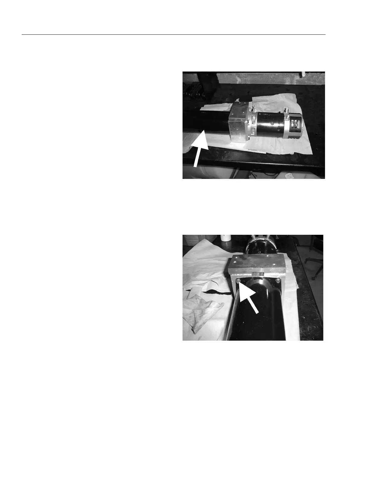
Pump Removal
1. Place the pump/motor assembly on a clean work-
bench.
NOTE: Drain the hydraulic oil by carefully removing the oil fill
plug located on the left side of the hydraulic reser-
voir.
2. Remove the oil tank from the lift cylinder as follows:
a. Slowly loosen and remove the four bolts that
hold the tank on to the cylinder.
b. Carefully remove the tank from the valve taking
care not to damage internal pickup tube or o-
ring gasket on tank.
c. Place tank on a suitable work bench or work
area.
NOTE: The filter and bypass are located on the pickup tube
inside the tank.
The filter should be changed once a year.