SECTION 4 - HYDRAULICS
3121166 – JLG Lift – 4-11
4.8 CYLINDER REPAIR
NOTE: The following are general procedures that apply to
all of the cylinders on this machine. Procedures that
apply to a specific cylinder will be so noted.
Disassembly
DISASSEMBLY OF THE CYLINDER SHOULD BE PERFORMED ON
A CLEAN WORK SURFACE IN A DIRT FREE WORK AREA.
1. Connect a suitable auxiliary hydraulic power source
to the port block fitting in the manifold located on the
cylinder.
DO NOT FULLY EXTEND CYLINDER TO THE END OF STROKE.
RETRACT CYLINDER SLIGHTLY TO AVOID TRAPPING PRES-
SURE.
2. Operate the hydraulic power source and extend the
cylinder. Shut down and disconnect the power
source. Adequately support the cylinder rod, if appli-
cable.
3. If applicable, remove the cartridge-type holding
valve and fittings from the cylinder port block. Dis-
card o-rings.
4. Place the cylinder barrel into a suitable holding fix-
ture.
5. Mark cylinder head and barrel with a center punch
for easy realignment. Loosen the cylinder head set-
screw.
NOTE: Steps 6 and 7 apply only to the steer cylinder.
6. Using a spanner wrench, loosen the spanner nut
retainer, and remove spanner nut from cylinder bar-
rel.
7. Being careful not to mar the surface of the rod, use a
punch or wooden dowel and hammer to drive the
rod guide about one inch down into the cylinder
bore. Using a screw driver, carefully push one end of
the round retaining ring back towards the inside of
the cylinder and then slip the screwdriver tip under
that end. Pull the ring out of the groove toward the
wall mouth. Once one end of the retaining ring is
free from the groove, the remainder can be easily
pried free using ones fingers or pliers.
8. Attach a suitable pulling device to the cylinder rod
port block end or cylinder rod end, as applicable.
EXTREME CARE SHOULD BE TAKEN WHEN REMOVING THE CYL-
INDER ROD, HEAD, AND PISTON. AVOID PULLING THE ROD OFF-
CENTER, WHICH COULD CAUSE DAMAGE TO THE PISTON AND
CYLINDER BARREL SURFACES.
9. With the barrel clamped securely, apply pressure to
the rod pulling device and carefully withdraw the
complete rod assembly from the cylinder barrel.
10. Using suitable protection, clamp the cylinder rod in
a vise or similar holding fixture as close to the piston
as possible.
NOTE: For steer cylinder piston removal, see Steer Cylin-
der Piston Removal - Cyl. p/n-1684456 on page 4-12
following.
11. Loosen and remove the cap screw(s), if applicable,
which attach the tapered bushing to the piston.
12. Insert the cap screw(s) in the threaded holes in the
outer piece of the tapered bushing. Progressively
tighten the cap screw(s) until the bushing is loose
on the piston.
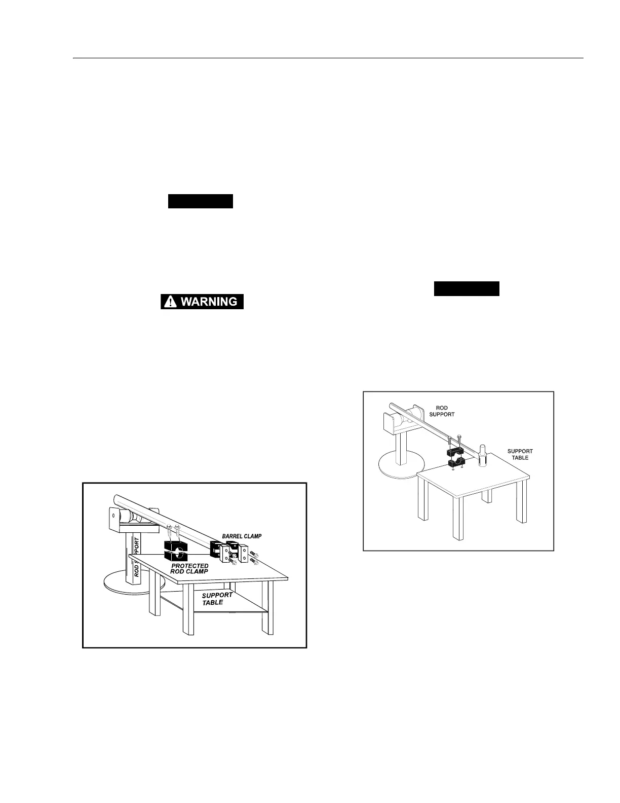
Figure 4-3. Cylinder Barrel Support
Figure 4-4. Cylinder Rod Support