SECTION 3 - CHASSIS & SCISSOR ARMS
3-52 – JLG Lift – 3121166
USA Built Machines S/N 0200170585 to Present &
Belgium Built Machines S/N 1200015159 to Present:
NOTE: The below procedures apply to 2030ES/2630ES/
2646ES/3246ES only.
BE SURE TO PULL THE BATTERY DISCONNECT ANYTIME WORK
IS BEING PERFORMED ON THE DRIVE MOTORS OR DRIVE
MOTOR CABLING.
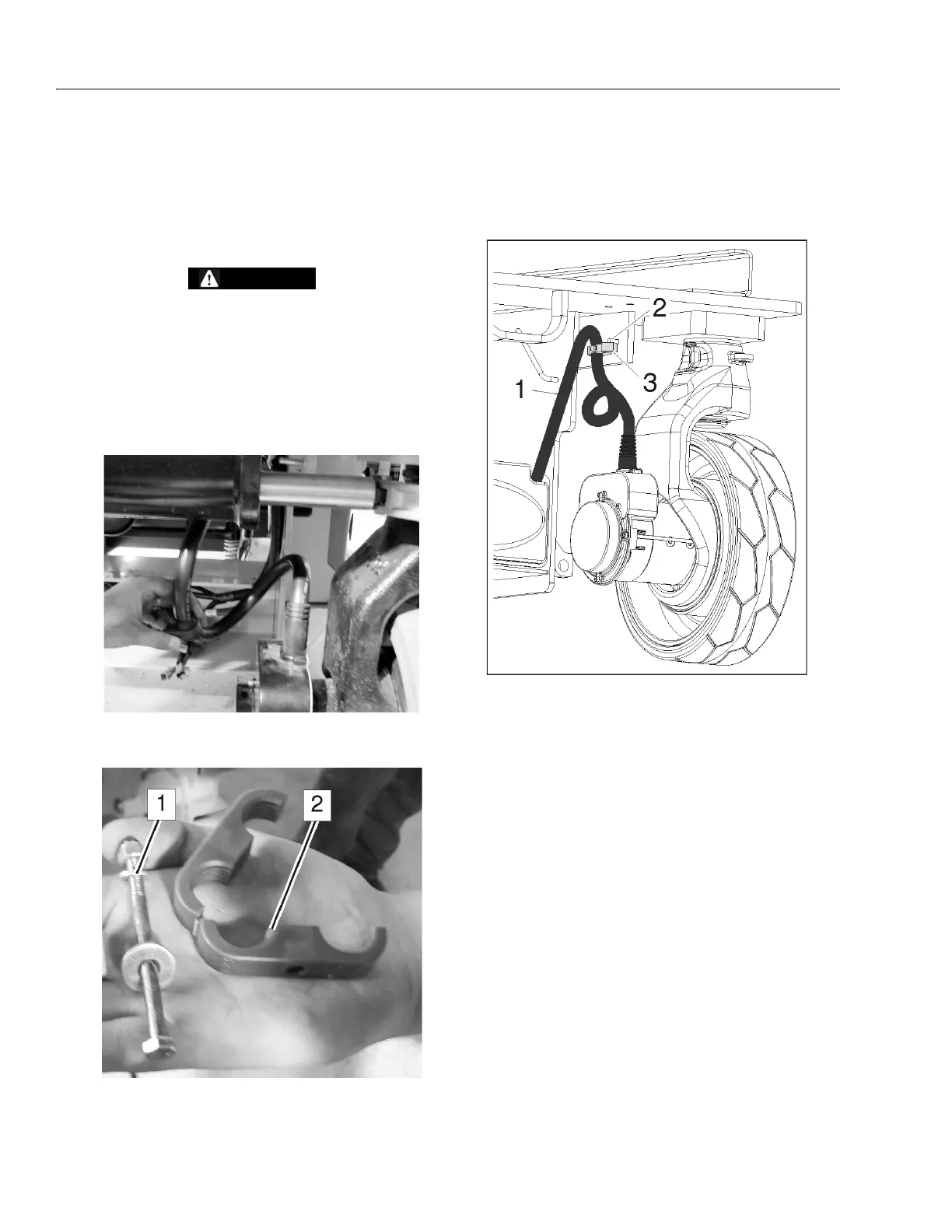
1. Orient the drive cables going back towards the rear
of the machine. Loop the cables forward towards the
front of the machine then up and back. Place the
Green Clamp on the clamping ring as shown below.
2. Obtain the Cable Clamp and hardware.
3. Bolt the Green Clamp onto the backside of the frame
using the the back hole drilled in step #4. The roll
pins inserted in the front-most holes act as a stop to
prevent the clamp from turning.
NOTE: When bolting the green clamp onto the frame, place
the larger washer against the clamp on the outside
of the clamp.
4. Connect the drive motor cables to the power mod-
ule..
5. Tuck all wires into the power module compartment
and install cover.
6. Reconnect battery cable plug. Power up machine
and operate the drive function to ensure drive
motors operate properly.
1. Bolt, Washers, and Nut
2. Cable Clamp
1. Drive Cable
2. Roll Pin
3. Cable Clamp