7 – 16
7.4
7
C
C
C
B
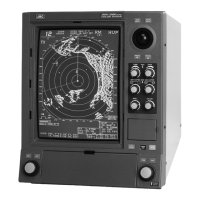
Fig. 7.6 Internal View of Modulator of 25kW Scanner Unit NKE-1056
D
D
D
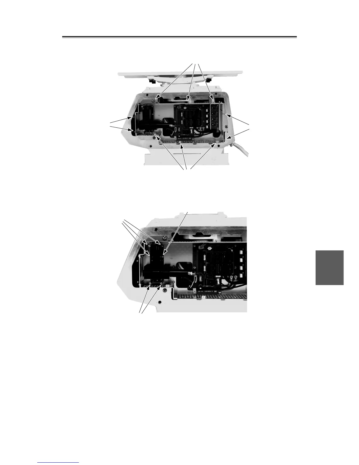
Fig. 7.7 Internal View of Modulator of 25kW Scanner Unit NKE-1056
[Replacement of Diode Limiter (A102)]
Remove the four screws fixing both the receiver and the PIN attenuator. Remove the four screws fixing the
diode limiter and another four screws fixing both the diode limiter and the PIN attenuator to take off the
diode limiter. When installing the new diode limiter, pay attention to its direction so that the arrow faces in
the direction of the receiver.
[Replacement of PIN Attenuator (A103)]
Remove the four screws fixing the PIN attenuator in the same way as for replacing the diode limiter and
remove the PIN attenuator.
 Loading...