D3-DU 3xx/A, /BConnections and wiring
Project engineering manual V1.09
68
© KEBA 2021
6.13 (Only for D3-DU 3x5/x) Digital outputs
The D3-DU 3x5/x offers 4 digital outputs (terminal X20A) with 0.5 A nominal
current for driving digital actuators.
For further information and connection examples, see safety manual "Func-
tional safety".
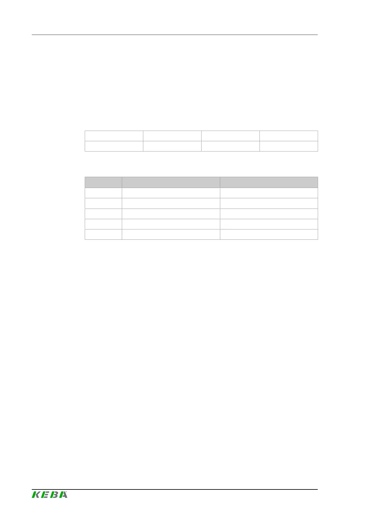
6.13.1 Pin assignment
4 5 6 7
0 1 2 3
Pin 0 corresponds to the upper left-hand pin of the connector on the front of
the module.
Pin no. Signal designation Description
0 DO0 Digital output (DO0)
1 DO1 Digital output (DO1)
2 DO2 Digital output (DO2)
3 DO3 Digital output (DO3)
4 - 7 GND Ground
6.14 EMC and wiring guidelines
Pay attention from the outset to careful wiring and shielding according to the
given guidelines.
Further information: See system manual.
 Loading...
