7-4 2G0947 - 31JAN08
Functional Diagrams
A B C D E F G H J K L M N P Q RST U V W X YZAA
T U V W X YZAAA B C D E F G H J K L M N P Q RS
16
15
14
13
12
11
10
9
8
7
6
5
4
3
2
1
16
15
14
13
12
11
10
9
8
7
6
5
4
3
2
1
2008 January Rev. A 2G0849
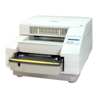
Kodak DryView 5800 LASER IMAGER - System Functional Block / Wiring Diagram - Sheet 4 of 4
- 6
- 4
- 3
- 1
Vacuum Valve
Upper
M3U
M5U
Pickup Drive
Motor - Upper
1
3
V REG
1
2
3
1
2
3
1
2
3
1
2
3
4
5
6
7
8
9
10
11
12
13
14
15
16
Upper
Pickup
1
2
3
4
5
6
7
8
9
10
11
12
13
14
- 6
- 4
- 3
- 1
Vacu um Va lve
Lower
M3L
M5L
Pickup Drive
Motor - Lower
1
3
1
2
3
1
2
3
1
2
3
Lower
Pickup
Cassette-In
Sensor - Upper
1
2
3
Cassette-In
Sensor - Lower
1
2
3
Film Saver
Sensor - Upper
1
2
3
Film Saver
Sensor - Lower
1
2
3
6
4
3
1
Film Tray
Unlock Motor
Upper
M6U
6
4
3
1
Film Tray
Unlock Motor
Lower
M6L
M1
Film Feed Roller
NIP Open/Close
Motor
6
4
3
1
M2
Film Feed Roller
Drive Motor
6
4
3
1
NIP Roller
Position Sensor
1
2
3
Vacuum
Pump
M4
1
2
1
2
3
4
5
6
7
8
9
10
11
12
13
14
15
16
17
18
19
20
Cassette
1
2
3
4
5
6
7
8
9
10
11
12
13
14
15
NIP
J13
1
2
3
4
5
6
7
8
9
10
11
12
13
14
15
16
17
18
19
20
21
22
23
J5
1
2
3
4
5
6
7
8
9
10
11
12
13
14
15
16
17
18
19
20
21
22
23
J4
5
6
7
8
9
10
11
12
M8
Processor Drum
Drive Motor
6
4
3
1
M9
Turnaround (Kick)
Roller Drive Motor
6
4
3
1
FPM
Board
Motor and Sensor Connections to the FPM Board
FPM Harness
Processor
Motor
1
2
3
4
5
6
J15
1
2
3
4
5
6
7
8
9
10
11
12
J14
1
2
3
4
5
6
7
8
9
10
11
12
13
14
J12
Lower
1
2
3
1
2
Upper
Film Separation
Fans
Intermediate
Connectors
FPM Board Intermediate
Connector
Motor or Sensor Wire
Color
Connector Pin Label Pin Designator Pin
5 5 1 WHT
6 6
M5U
3 RED
14 1 1
BRN
13 2 3
RED
12 3 4
ORN
J13
11 4
M3U
6
YEL
4 7 1
RED
2 8 2
GRN
6 9
S1U
3
BLK
13 10 1
RED
11 11 2
GRN
9 12
S2U
3
BLK
16 13 1
RED
14 14 2
GRN
J5
12
UPPER
PICKUP
15
S3U
3
BLK
4 5 1
WHT
5 6
M5L
3
RED
13 1 1
BRN
12 2 3
RED
11 3 4
ORN
J12
10 4
M3L
6 YEL
4 7 1
RED
2 8 2
GRN
6 9
S1L
3
BLK
13 10 1
RED
11 11 2
GRN
9 12
S2L
3
BLK
16 13 1
RED
14 14 2
GRN
J4
12
LOWER
PICKUP
15
S3L
3
BLK
FPM Board Intermediate
Connector
Motor or S
ensor
Connector Pin Label Pin Designator Pin
Wire
Color
19 7 1
RED
23 8 2
GRN
J5
21 9
S5U
3
BLK
19 10 1
RED
23 11 2
GRN
J4
21 12
S5L
3
BLK
1 1 1
RED
5 2 2
GRN
J5
3 3
S6U
3
BLK
1 4 1
RED
5 5 2
GRN
J4
3 6
S6L
3
BLK
10 13 1
BRN
9 14 3
RED
8 15 4
ORN
J13
7 16
M6U
6
YEL
9 17 1
BRN
8 18 3
RED
7 19 4
ORN
J12
6
CASSETTE
20
M6L
6
YEL
4 5 1
BRN
3 6 3
RED
2 7 4
ORN
J14
1 8
M1
6
YEL
6 1 1
BRN
5 2 3
RED
4 3 4
ORN
J15
3 4
M2
6
YEL
22 9 1
RED
20 10 2
GRN
J5
18 11
S4
3
BLK
1 12 1
RED
2 13
M4
2
BLK
3 14 1
RED
2
BLK
J13
4 15
Film
Separation
Fans –
Upper and
Lower
3 Not
Used
99
1
BRN
10
10
3
RED
11
11
4
ORN
12
12
M8
6
YEL
5
5
1
BRN
66
3
RED
77
4
ORN
J14
8
Processor
Motors
8
M9
6
YEL
NIP
V REG
V REG
Pickup Home
Sensor - Upper
Film Contact
Sensor - Upper
Film Separated
Sensor - Upper
S1U
S2U
S3U
V REG
V REG
V REG
Pickup Home
Sensor - Lower
Film Contact
Sensor - Lower
Film Separated
Sensor - Lower
S1L
S2L
S3L
V REG
V REG
V REG
V REG
S5U
S5L
S6U
S6L
V REG
S4
1
2
3
4
5
6
7
8
9
10
11
12
13
14
15
16
Pins 1-4 NU
Pins 16-20 NU
Pins 21-24 NU
NU
NU
Upper Pickup
Harness
Lower Pickup
Harness
Processor Motor
Harness
Pins 7, 8, 10, 15, 17
and 24 -30 NU
NU
Pins 7, 8, 10,
15, 17, 20, 22
and 24 -32 NU
NU
NU = Not Used
Cassette
Harness

 Loading...

