2G0947 - 31JAN08 5-117
Diagnostics
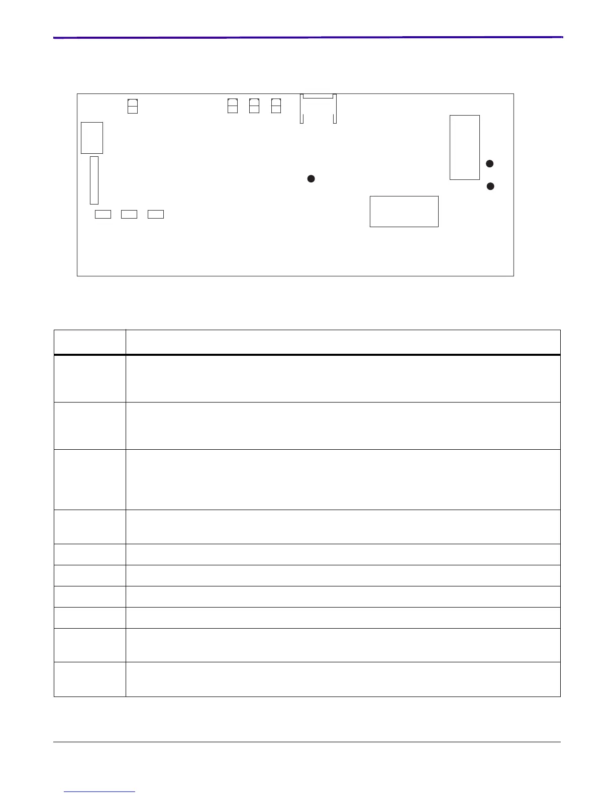
PROCESSOR CONTROL BOARD (PCB)
Table 5-8: PCB LEDs and Test Points
Item Description
D2 CONFIG LED - When lit, the AC line voltage is 88 - 140 V AC (the 2 DRUM HEATERS are
connected in parallel). When unlit, the voltage is 173 - 264 V AC (the 2 DRUM HEATERS are
connected in series).
D4 INTLK LED - When lit, the MICROCONTROLLER has enabled the line voltage to the DRUM
HEATER. This LED will be OFF briefly at times, but during normal operations is continuously
lit.
D5 "Happy" LED - When the MICROCONTROLLER is functioning normally, this LED blinks
slightly faster than once a second. During MICROCONTROLLER reflash, the LED may freeze
momentarily. If the LED is steady ON or steady OFF, the MICROCONTROLLER is not
functioning.
D6 SSR LED - This LED pulses ON and OFF in 2 second cycles as the Solid State Relay (SSR)
switches HEATER power ON and OFF.
JP1 Test point for +3.3 V.
JP2 Test point for +2.5 V.
JP3 Test point for Ground.
+24VTEST Test Point for Hazard 24 V.
LINE,
NEUTRAL
Test points for AC line voltage at the input of the PCB.
S1 RESET SWITCH - Pressing this SWITCH causes a Checksum and Memory test to run for the
software on the PCB.
JP3 JP1 JP2
S1
J3
J1
J4
J6
D5 D2 D4 D6
+24VTEST
NEUTRAL
LINE
PCB

 Loading...