GL16 Repair
7-39
6. Disconnect the touchless temperature sen-
sor cooling tube (Figure 7-37, A) from the
holding tube (B).
7. Remove the holding tube (Figure 7-37, B).
8. Begin to remove the burner by removing
the pilot gas line tube (Figure 7-38, A).
9. Remove the pilot air line (Figure 7-38, B).
10. Remove the ignition wire from the spark
plug (Figure 7-38, C).
11. Remove the spark plug (Figure 7-38, D).
12. Carefully remove the pilot assembly from
the burner by turning counter clockwise
(Figure -38, E).
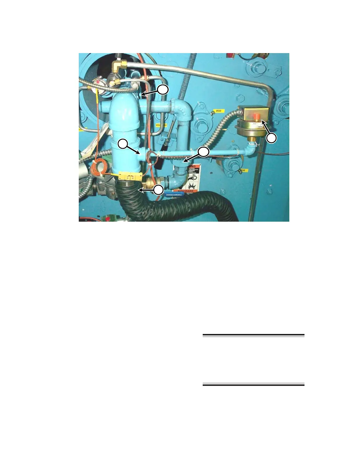
13. Remove the combustion blower air hose
(Figure 7-39, A) from the burner assem-
bly.
14. Disconnect the cable and wire inside the
combustion air pressure switch (Figure
7-39, B).
15. Remove the air pressure switch and the
connecting pipe by unscrewing the pipe
where it joins the air mixer (Figure 7-39,
C).
16. Loosen the union (Figure 7-39, D) be-
tween the gas valve and the air mixer.
NOTE: Three maintenance
people are required to remove the
burner assembly. Station one
person at the right end of the unit
and the other two at the left end.
Figure 7-39: Burner system.
E
D
B
C
 Loading...