Installation GL16
2-8
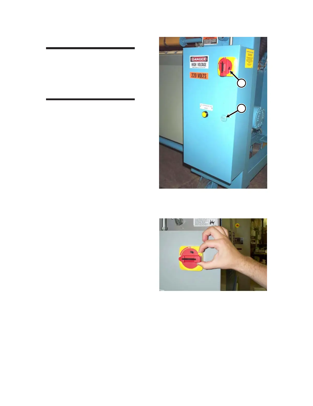
Figure 2-13: Rotate the yellow lever and hold
against the red main disconnect
switch to open or close the main
electrical box.
B
Figure 2-12: The main disconnect switch (A) and
latch (B) secure the door of the main
electrical box.
Main Power Connection
WARNING
Only a qualified electrician
should make the electrical
connections to the unit.
Improper installation could
result in serious injury.
1. Turn the main disconnect switch to the
OFF position (Figure 2-12, A). The main
disconnect switch is located on the main
electrical box at the rear of the left end
frame.
2. Unlock the door latch (Figure 2-12, B) on
the main electrical box.
3. With the main disconnect switch in the
OFF position, rotate the yellow lever
clockwise; hold yellow lever against the
red main disconnect switch (Figure 2-13),
then open the main electrical box.
4. Bring the supply lines to the main electri-
cal box. Use three wires for the power
supply and a green fourth wire for ground.
5. Extend the lines through conduit or
greenfield.
6. Temporary red wires can be seen extend-
ing from the main disconnect switch and
out through the main electrical box. Pull
these wires back through the hole and out
of the way.
7. Pull the external wiring through the hole
and secure the conduit or greenfield to
the main electrical box.
 Loading...