Installation GL16
2-10
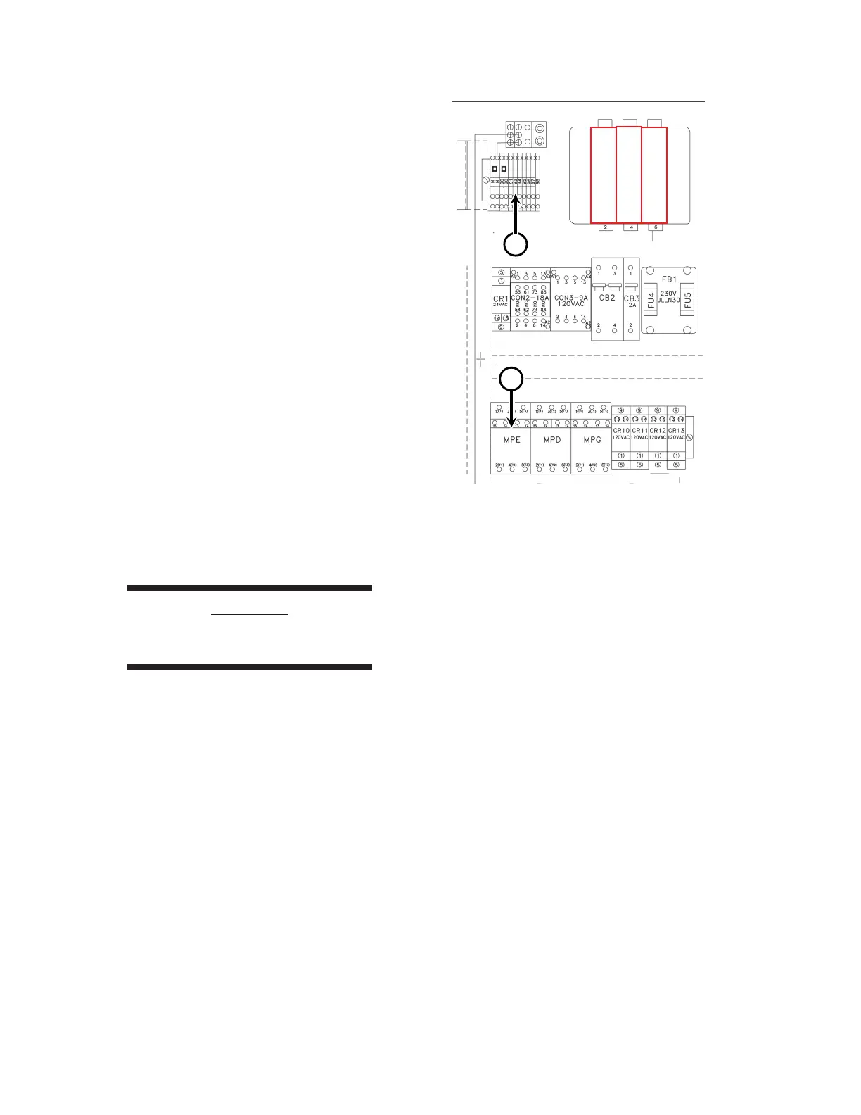
3. Connect the three purple wires for the ex-
haust blower motor to the exhaust blower
motor protector (labeled CANOPY MO-
TOR) in the main electrical box. (Figure
2-16, A).
4. The electrical connections for the two sail
switch wires are made in the upper left of
the main electrical box.
5. Locate the sail switch connection card
(Figure 2-16, B) attached to the jumper
wire at the upper left of the box (terminal
90 to 91).
6. Remove the jumper wire and connect the
two red wires from the sail switch to these
terminals.
7. After all electrical connections have been
made, close the main electrical box door.
Rotate and hold the yellow lever while
holding the main disconnect switch in the
OFF position (Figure 2-13). Gently push
the door closed and turn the door latch
clockwise.
CAUTION
Do not attempt to start the
unit at this time.
Figure 2-16: Electrical connections for the exhaust
blower motor (A) and sail switch (B).
B
 Loading...