114 WM-OM-E Rev I
4. Select Positive or Negative slope.
5. Touch inside the After data entry field and select the qualifying signal source from the
pop-up menu. If you select an input channel or external source, touch inside the has gone
data entry field and select a logic level: Above or Below. Then touch inside the Level field
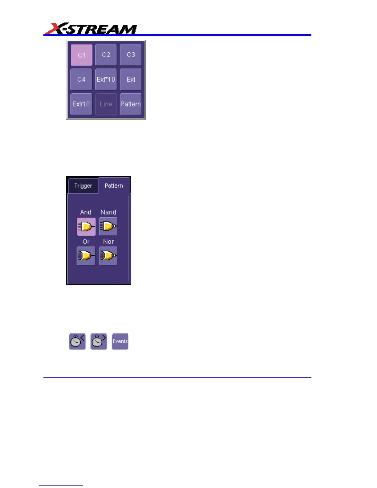
and set a voltage level using the pop-up numeric keypad. If you select Pattern from the
pop-up menu, touch the Pattern tab and choose a logic gate:
.
Then touch inside the State field for each channel input you want to use in the pattern and
select a logic condition: High or Low. Select Don't Care for unused inputs. For the inputs
to be used, touch inside each Level field and enter a voltage threshold using the pop-up
numeric keypad. Then touch the Trigger tab again.
6. If you want to set a holdoff in time or events, touch one of the Qualify by: buttons:
, , .
7. Touch inside the field below the Qualify by: buttons and enter a value using the numeric
keypad.