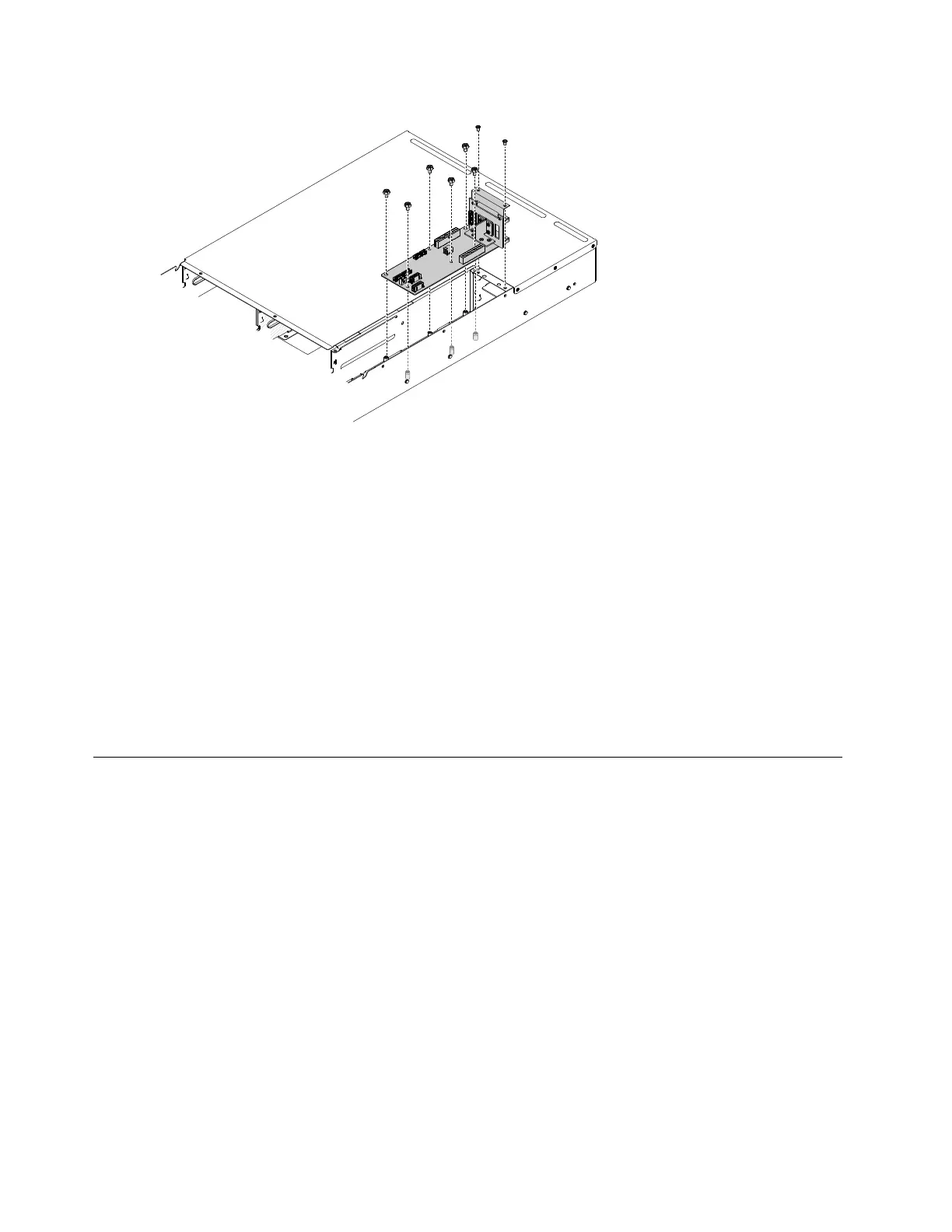
Figure90.systemmanagementboardandbackplaneassemblyinstallation
Step2.Tightenthesystemmanagementboardwith66#32screws.
Step3.Tightenthesystemmanagementboardwith2M3screws.
Step4.Reinstallthecables(see“Internalcableroutingandconnectors”onpage144).
Step5.Reinstallthesystemmanagementboardcover(see“Installingthesystemmanagementboard
cover”onpage85
).
Step6.Reinstallthefancagecover(see“Installingthefancagecover”onpage83).
Step7.Reinstallthepowersupplies(see“Replacingahot-swappowersupply”onpage99).
1.Installtheserverintotherackenclosureandpushtheserverintotherackuntilitclicksintoplace.
2.Reconnectthepowercordsandanycablesthatyouremoved.
3.Turnontheperipheraldevicesandtheserver.
Internalcableroutingandconnectors
Thissectionprovidesinformationaboutroutingthecableswhenyouinstallsomecomponentsintheserver.
Notes:
•Turnofftheserverandperipheraldevicesanddisconnectthepowercordsandallexternalcablesbefore
routingthecables.
•Alwaysmatchthenumbersontheprintedcircuitboardsandthenumbersonthecablestoconnect
thecables.
Formoreinformationabouttherequirementsforcablesandconnectingdevices,seethedocumentation
thatcomeswiththesedevices.
Thefollowingillustrationdisplaysthecablinginformationonthefanboard:
144LenovoThinkServersd350ServerType5493,LenovoThinkServern400EnclosureType5495InstallationandServiceGuide