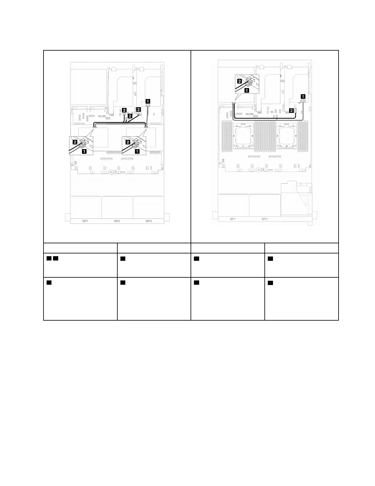
Middle/Rear backplane cable routing
Figure 335. Middle backplane cable routing
Figure 336. Rear backplane cable routing
From To From To
1 1
• Backplane 5: SAS
• Backplane 6: SAS
1 16i adapter
• Gen 4: C1
• Gen 3: C2C3
1 Backplane 4: SAS
1 16i adapter
• Gen 4: C0
• Gen 3: C0C1
2
• Backplane 5: PWR
• Backplane 6: PWR
2
• Onboard: rear
backplane power
• Onboard: rear
backplane sideband
• Riser 1: PWR
2 Backplane 4: PWR
2 Onboard: 7mm power
connector
Two 8 x AnyBay backplanes
This section provides cable routing information for the server model with two 8 x 2.5-inch AnyBay front
backplanes.
To connect power cables for the front backplane(s), refer to
“Backplanes: server models with 2.5-inch front
drive bays” on page 312
.
To connect signal cables for the front backplane(s), refer to the following cable routing scenarios depending
on your server configuration.
• “Trimode 8i RAID adapter” on page 340
• “Trimode 16i RAID adapter” on page 340
Chapter 6. Internal cable routing 339

 Loading...


