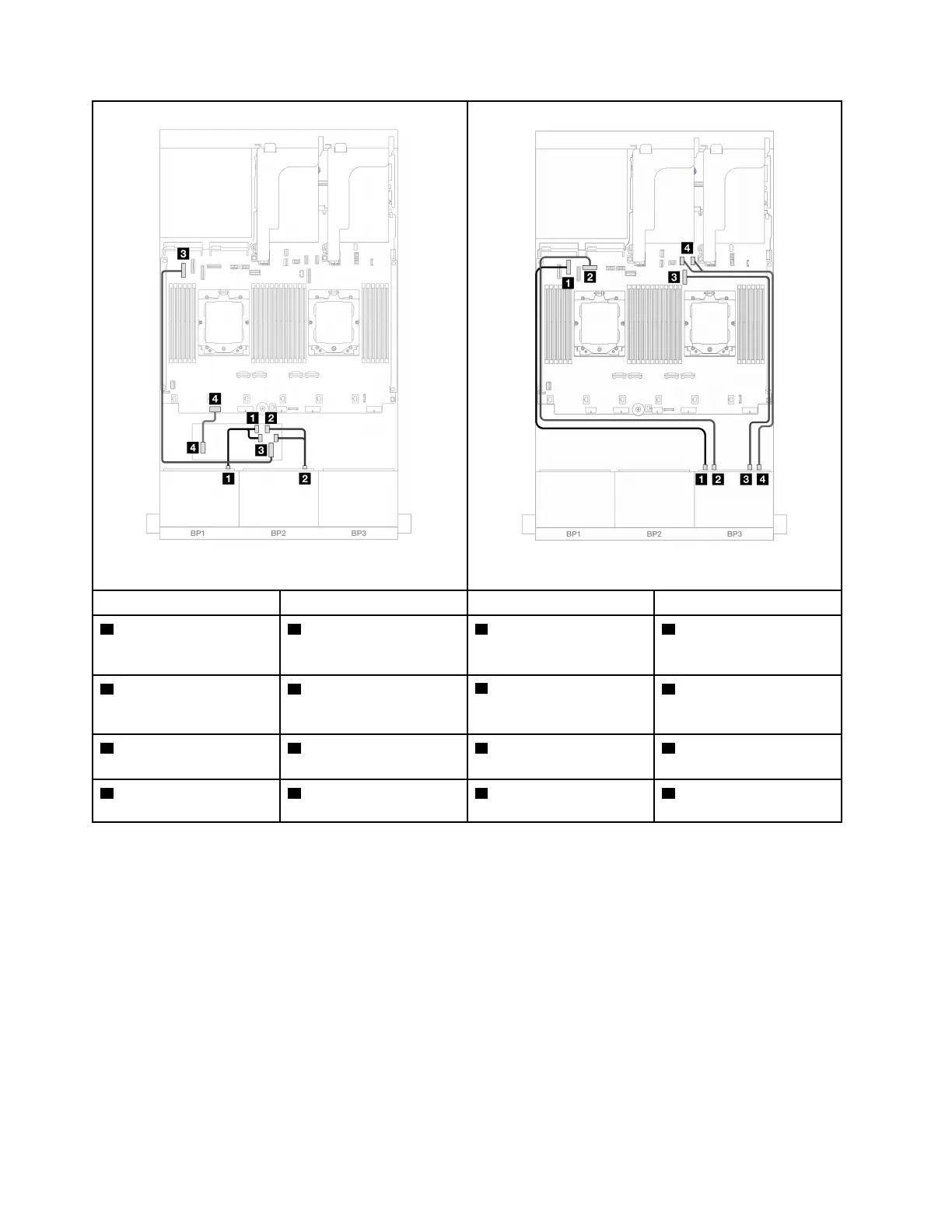
Figure 455. Cable routing to CFF adapter
Figure 456. NVMe cable routing
From To From To
1 Backplane 1: SAS 1 CFF adapter
• C0
• C1
1 Backplane 3: NVMe 0-1
1 Onboard: PCIe 6
2 Backplane 2: SAS 2 CFF adapter
• C2
• C3
2 Backplane 3: NVMe 2-3
2 Onboard: PCIe 8
3 CFF adapter: MB (CFF
INPUT)
3 Onboard: PCIe 5
3 Backplane 3: NVMe 4-5
3 Onboard: PCIe 9
4 CFF adapter: PWR 4 Onboard: CFF RAID/
HBA PWR
4 Backplane 3: NVMe 6-7
4 Onboard: PCIe 10, 11
Two 8 x SAS/SATA and one 8 x NVMe (Gen 5) backplanes
This section provides cable routing information for the server model with two 8 x 2.5-inch SAS/SATA and one
8 x 2.5-inch NVMe (Gen 5) front backplanes.
To connect power cables for the front backplane(s), refer to
“Backplanes: server models with 2.5-inch front
drive bays” on page 312
.
To connect signal cables for the front backplane(s), refer to the following cable routing scenarios depending
on your server configuration.
• “8i RAID/HBA adapter” on page 421
• “8i RAID/HBA adapter + Retimer card” on page 427
• “16i RAID/HBA adapter” on page 423
• “16i RAID/HBA adapter + Retimer card” on page 429
426
ThinkSystem SR665 V3 User Guide

 Loading...


