The OCP module provides two or four extra Ethernet connectors for network connections. By default, any of
the connectors on the OCP module can function as a shared management connector.
Top view
This section contains information on the top view of the server.
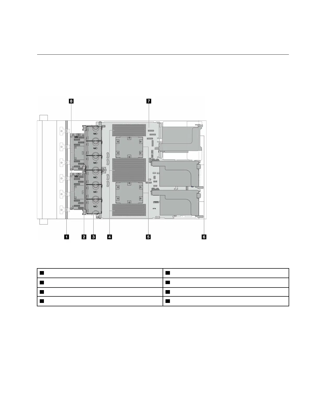
The following illustration shows the top view of the server without any air baffle, middle cage, or rear cage
installed.
Figure 9. Server top view
Table 19. Component identification (Top view)
1 Front backplane(s)
2 Intrusion switch
3 System fans
4 Memory modules
5 Processors and heat sinks 6 Riser assemblies
note 1
7 System board assembly 8 CFF RAID adapter/expander
note 2
Notes:
1. The illustration shows the server rear configuration with three riser assemblies. The server rear
configurations vary by server model. For details, see
“Rear view” on page 24.
2. The illustration shows the server with CFF adapters which are available only in the 2.5-inch chassis. In
some configurations, there might be installed with a RAID flash power module. For details, see
Table 25
“Location of RAID flash power modules” on page 190
.
Chapter 2. Server components 29

 Loading...


