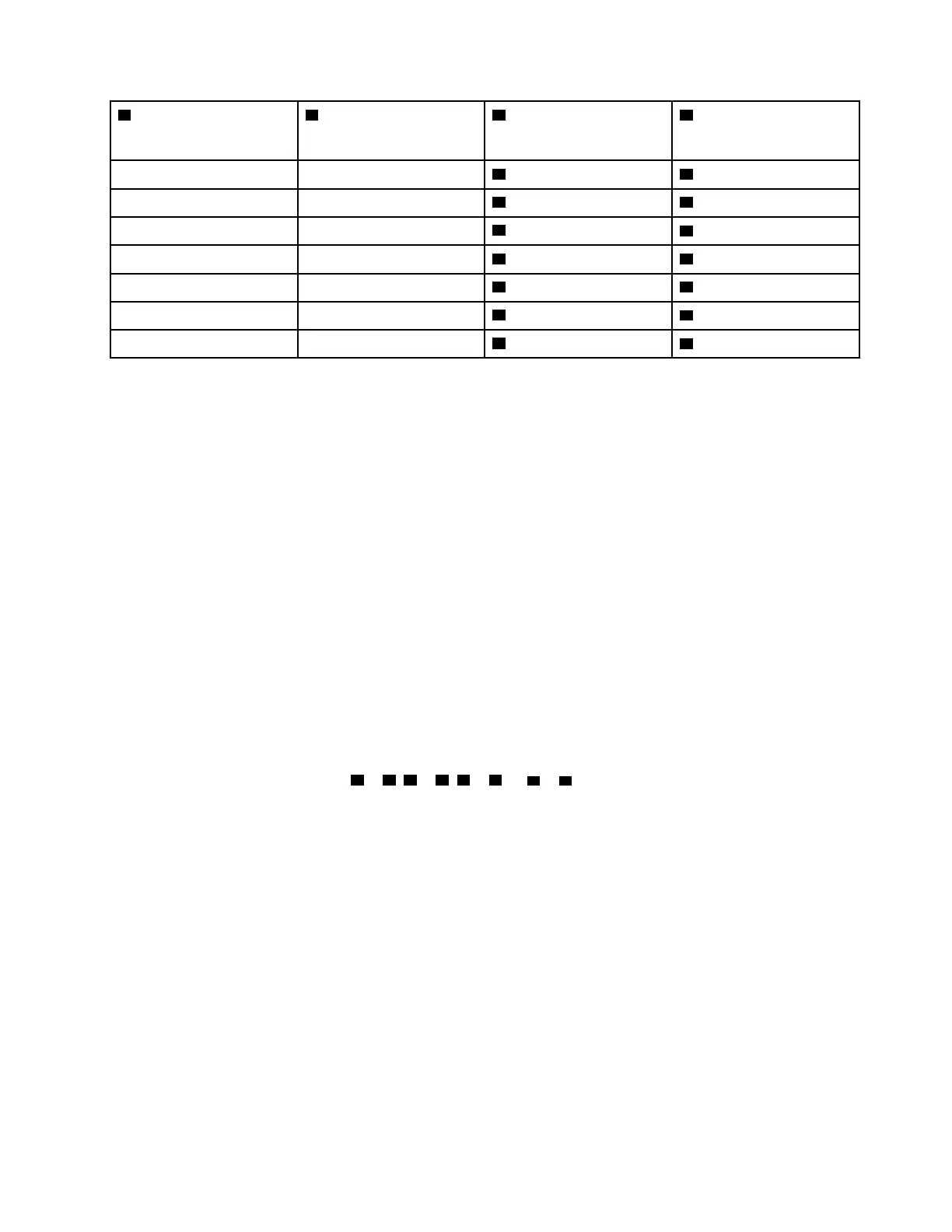
1 Backplane 1: SAS
1 8i adapter
• Gen 4: C0
• Gen 3: C0C1
1 Backplane 2: NVMe 0-1
1 Onboard: PCIe 6
2 Backplane 2: NVMe 2-3
2 Onboard: PCIe 8
3 Backplane 2: NVMe 4-5
3 Onboard: PCIe 5
4 Backplane 2: NVMe 6-7
4 Onboard: PCIe 7
5 Backplane 3: NVMe 0-1
5 Retimer card: C0
6 Backplane 3: NVMe 2-3
6 Retimer card: C1
7 Backplane 3: NVMe 4-5
7 Onboard: PCIe 9
8 Backplane 3: NVMe 6-7
8 Onboard: PCIe 10, 11
Two 8 x SAS/SATA and one 8 x AnyBay (Gen 4) backplanes
This section provides cable routing information for the server model with two 8 x 2.5-inch SAS/SATA and one
8 x 2.5-inch AnyBay (Gen 4) front backplanes.
To connect power cables for the front backplane(s), refer to
“Backplanes: server models with 2.5-inch front
drive bays” on page 312
.
To connect signal cables for the front backplane(s), refer to the following cable routing scenarios depending
on your server configuration.
•
“32i RAID/HBA adapter” on page 415
• “8i RAID/HBA adapters” on page 417
32i RAID/HBA adapter
The following shows the cable connections for the front (16 x 2.5-inch SAS/SATA + 8 x 2.5-inch Gen 4
AnyBay) configuration with one 32i RAID/HBA adapter.
To connect the processor interconnection cable when two processors are installed, see
“Processor
interconnection cable routing” on page 311
.
Connections between connectors:
1 ↔ 1 , 2 ↔ 2 , 3 ↔ 3 , ... n ↔ n
Chapter 6
. Internal cable routing 415

 Loading...


