Figure 461. SAS/SATA cable routing
Figure 462. NVMe cable routing
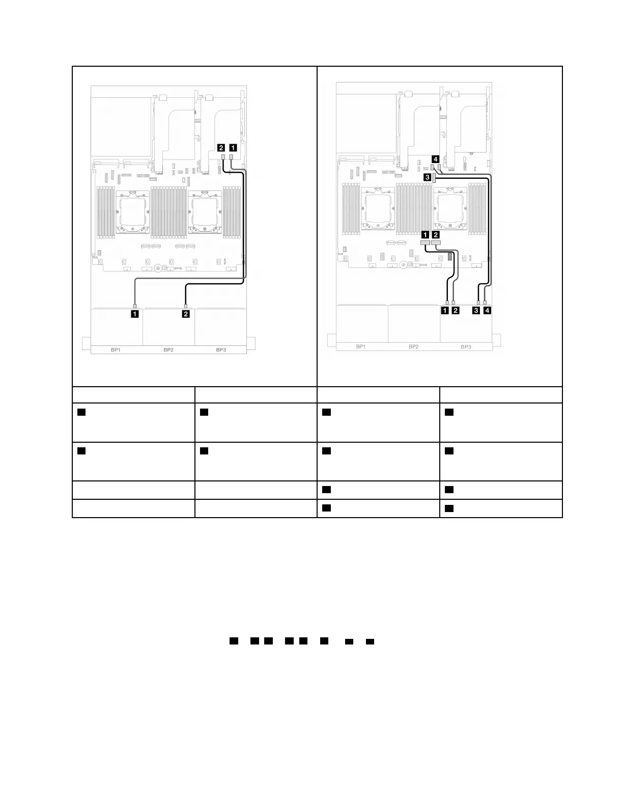
From To From To
1 Backplane 1: SAS
1 16i adapter
• Gen 4: C0
• Gen 3: C0C1
1 Backplane 3: NVMe 0-1
1 Onboard: PCIe 2
2 Backplane 2: SAS
2 16i adapter
• Gen 4: C1
• Gen 3: C2C3
2 Backplane 3: NVMe 2-3
2 Onboard: PCIe 1
3 Backplane 3: NVMe 4-5
3 Onboard: PCIe 9
4 Backplane 3: NVMe 6-7
4 Onboard: PCIe 10, 11
16i RAID/HBA adapter + Retimer card
The following shows the cable connections for the front (16 x 2.5-inch SAS/SATA + 8 x 2.5-inch Gen 5
NVMe) configuration with one 16i RAID/HBA adapter and one retimer card when two processors are
installed.
To connect the processor interconnection cable when two processors are installed, see
“Processor
interconnection cable routing” on page 311
.
Connections between connectors:
1 ↔ 1 , 2 ↔ 2 , 3 ↔ 3 , ... n ↔ n
Chapter 6
. Internal cable routing 429

 Loading...


