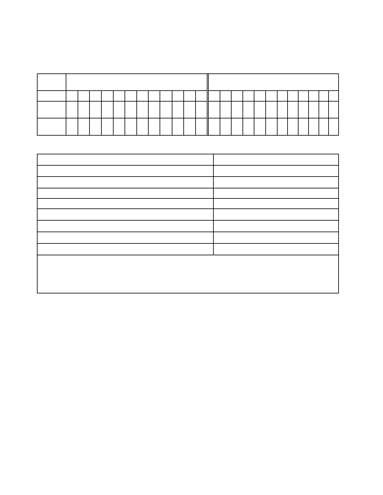
The memory-channel configuration table below shows the relationship between the processors, memory
controllers, memory channels, and memory module slot numbers.
Table 22. Memory slot and channel identification
Process-
or
Processor 2 Processor 1
UMC No. 2 1 5 0 4 3 9 10 6 11 7 8 2 1 5 0 4 3 9 10 6 11 7 8
Channel
No.
F E D C B A G H I J K L F E D C B A G H I J K L
DIMM
No.
24 23 22 21 20 19 18 17 16 15 14 13 12 11 10 9 8 7 6 5 4 3 2 1
General DIMM mixing rules
DIMMs
Coexist in a system
9x4 RDIMM and other RDIMM types
x
3DS RDIMM and other DIMM types
x
128 GB 3DS RDIMM and 256 GB 3DS RDIMM
x
x4 DIMM and x8 DIMM
x
16 Gbit (16 GB/32 GB/64 GB) DIMM and 24 Gbit (96 GB) DIMM
x
DIMMs with different capacity
√
Single-rank DIMM and dual-rank DIMM
√
DIMMs manufactured by different vendors
√
Notes:
• When installing DIMMs with different capacity, install the DIMM with the highest capacity first following the
population sequence.
• For optimal performance, it is recommended to install DIMMs with identical capacity and rank in the same channel
of the two processors.
Memory module installation order
Notes: In the following tables:
• S1–S24 indicate DIMM slots 1–24.
• 1–24 indicate the installation order.
For example, when 12 DIMMs are installed for two processors, the installation order is slot 7, 19, 6, 18, 9, 21,
4, 16, 8, 20, 5, 17.
52
ThinkSystem SR665 V3 User Guide

 Loading...


