Page 44 of 88 TP1A072–3 English
Aug 2017
Linx 10 Operating Manual —
Line and message settings
Linx 10
5.2.7 Photocell Type
NOTE: This option is not available if you select the Line Sensor option.
This option allows you to specify the type of photocell used to trigger a print (either NPN or PNP).
Touch the Photocell Type button to display the Photocell Type screen. Touch the name of the
required type to select that type.
5.2.8 Photocell Deadtime
NOTE: This option is not available if you select the Line Sensor option.
This option allows you to set a delay period for a photocell during which the photocell does not
respond to any trigger signals. This allows the printer to filter out any potential false trigger signals
caused by, for example, printing on a reflective substrate. You can set the deadtime period to 0 ms,
1ms, or 5ms.
5.2.9 Primary Photocell
NOTE: This option is not available if you select the Line Sensor option.
This option allows you to set the Photocell Type and Photocell Deadtime options for a primary
photocell on a printer (see above).
5.2.10 Secondary Photocell
NOTE: This option is not available if you select the Line Sensor option.
This option allows you to set the Photocell Type and Photocell Deadtime options for a secondary
photocell on a printer (see above).
5.2.11 Inter-Print Distance
NOTE: This option is not available if you select the Line Sensor option.
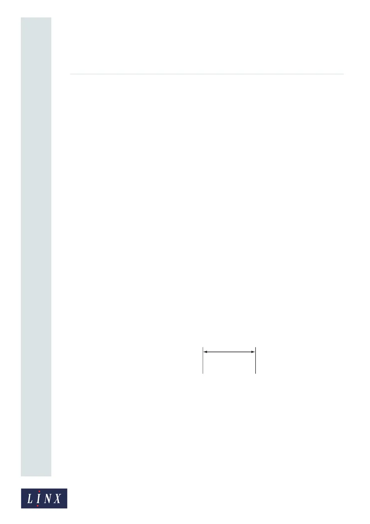
The Inter-Print Distance is the distance between the end of one message and the end of the next
message—the dimension “A” in Figure 35.
Figure 35. Inter-Print Distance
The Inter-Print Distance is used only for continuous printing. (For continuous printing, set the Print
Trigger option to Continuous). Touch this button to display the Enter Inter-Print Distance screen,
and then enter the required value.
5.2.12 Maximum Line Speed
This option is only visible when the Shaft Encoder speed mode is selected on the Line Settings
screen.