Page 49 of 88 TP1A072–3 English
Aug 2017
Linx 10 Operating Manual —
Line and message settings
Linx 10
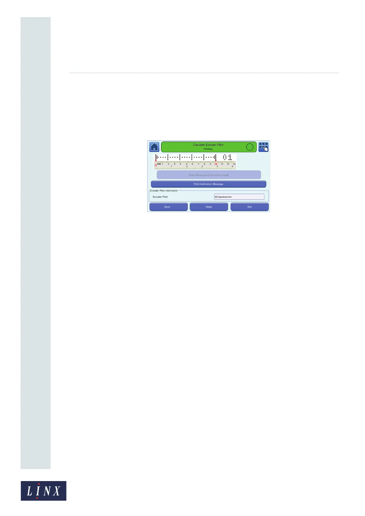
7 Touch the Enter Measured Calibration Length button to display the Measured Calibration
Length screen (see Figure 39 on page 47).
8 Enter the measured calibration length (for example 75 mm) and touch the Save button. The
printer calculates the encoder pitch from the entered measurement and displays the
Calculate Encoder Pitch screen. The printer displays the calculated encoder pitch in the
“Encoder Pitch Information” box.
Figure 43. Calculate Encoder Pitch: encoder pitch calculated screen
9 Touch the Stop button to pause the print or touch the Reset button to return to the previous
encoder pitch value. Touch the Save button to save the new calculated encoder pitch.
5.4 24 V alarm
The printer can use a 24 V alarm connection The alarm controls internal alarm tones and alarm
output signals. You can use the alarm output signals to control external alarm beacons.
You can use the 24 V alarm to indicate a range of system events, for example, Faults and Warnings.
The alarm operates in one of the following modes:
• Continuous—the alarm is turned on and remains on until the alarm condition is cleared.
• Pulsed Continuous—the alarm pulses continuously until the alarm condition is cleared.
• Pulsed—the alarm pulses twice if an alarm condition occurs.
• None—no alarm is set.
You can use any of the alarm indication modes to indicate any alarm condition.