L-VIS User Manual 180 LOYTEC
Version 6.2 LOYTEC electronics GmbH
choose to generate one data point of direction value instead of two separate data points.
This data point can be read and written, so the desired direction will have to be specified at
each place the data point is used, whereas it is implicitly known with separate data points.
10.1.9 Structures
Complex data belonging semantically together may be structured. The data point model
allows mapping structure types onto user-defined data points of variant type. This can be
necessary, if a network technology carries such structured data or if a user-defined register
shall provide structured data for access through a single data point. In any case, the
structure is modeled as a top-level data point and a hierarchy of sub-data points
representing the structure members.
The top-level data point is a user data point of variant data type. It contains the image of the
entire structure as a Byte array. Each structure field is then modeled as a sub-data point of
the appropriate class (e.g. analog, binary, or multi-state). A structure field may itself be a
structure going down one level in the hierarchy of sub-data points.
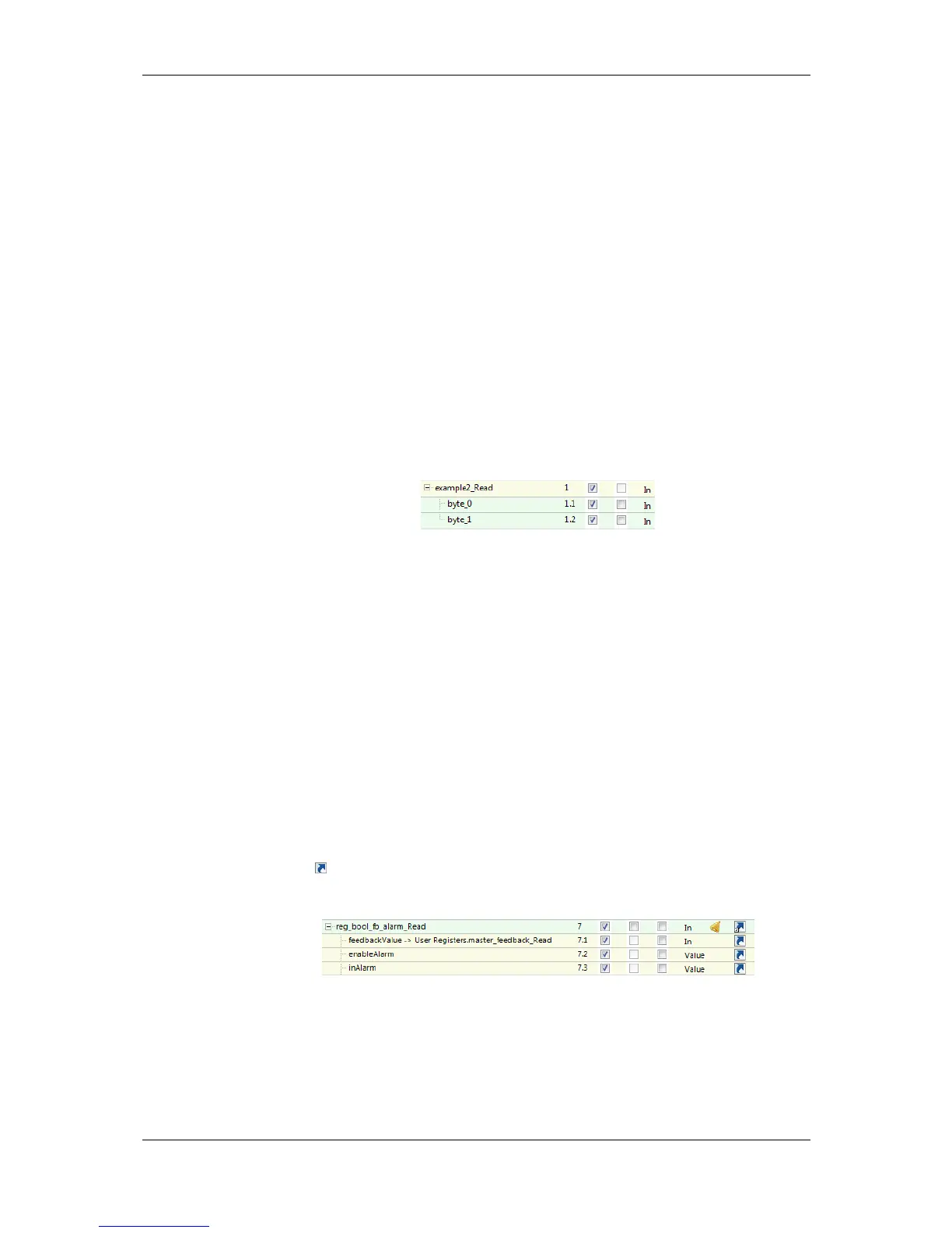
An example is shown in Figure 3. In this case a user register of two Bytes is bound to a
structure type mapping the two bytes on analog data points. The two sub data points byte_0
and byte_1.
Figure 3: Example of a structured data point.
The structure types are available in a type repository. This repository is divided into scopes.
Within each scope a type has a unique name. When selecting a type, the scope and the type
name needs to be specified.
10.1.10 Property Relations
A data point possesses a number of properties which influence the behavior and appearance
of the data point. Examples are data point name, poll cycle, or alarm limits. Most of those
properties are determined by the configuration and are static during operation of the device.
Some of those properties, however, can get a default value from the configuration and be
modified during run-time later on.
In some cases, property values need to be updated by other data points, e.g. a user register
or a technology data point. In this case, the data point property is linked to another data
point, following a given semantic relation. This is modeled as a property relation. Property
relations appear as data point links with the respective property names underneath their
governing data point. An example is shown in Figure 4. Relations are marked with a link
symbol . When hovering with the mouse over the link symbol, a bubble help appears
describing the property relation.
Figure 4: Example of property relations.
The property relations can be accessed like regular child data points. For this type of use,
no linkage against other data points is necessary. Property relations may, however, also be
linked to other data points, e.g. ‘feedbackValue’ in Figure 4. In this case, the linked data
point is used as the related property. The user may right-click on a linked property relation
and choose Go to related data point from the context menu. For mass engineering
property relation links to other data points refer to Section 10.6.9.