L-VIS User Manual 231 LOYTEC
Version 6.2 LOYTEC electronics GmbH
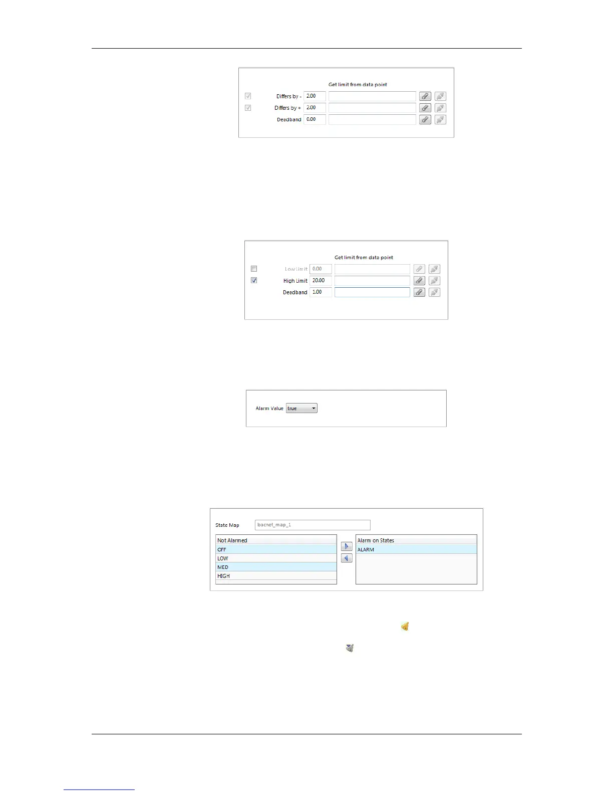
Figure 29: Condition for an Analog Feedback Alarm.
11. For an analog value condition, fill in the alarm condition as shown in Figure 30. Select
Low Limit and High Limit and put check marks, if they shall be employed. Enter a
Deadband to account for hysteresis. Attach or detach data points for those limits. This
can also be done by editing the property relations ‘lowLimit’, ‘highLimit’, and
‘deadband’, respectively (see Section 10.6.9).
Figure 30: Alarm Condition for an Analog Value Condition.
12. For a binary data point, define an alarm value in the alarm condition as shown in
Figure 31. Select the Alarm Value which triggers the alarm.
Figure 31: Alarm Condition for a Binary Data Point.
13. For a multi-state data point, define the alarm values in the alarm condition as shown in
Figure 32. Select the states in the list Not Alarmed and move them to Alarm on
States by clicking the arrow buttons.
Figure 32: Alarm Condition for a Multi-State Data Point.
14. Click on Create. In the alarm column, the alarm sign will be added for those data
points that have an alarm condition. If a sub-data point has been alarmed, the top-level
data point will indicate this with the sign .
10.11.3 Deliver Alarms via E-mail
Updates in the alarm summary of an alarm object can be used as a trigger to send e-mail.
For setting up e-mails, the account information has to be configured on the device, e.g., on
the web UI. Then an e-mail template can be created and the alarm point attached as a