L-VIS User Manual 209 LOYTEC
Version 6.2 LOYTEC electronics GmbH
NOTE: By default, only compatible data points are displayed. Sometimes compatible data points
are available as member points (e.g., a SNVT structure member). Expand the data point
and select the desired member point if required.
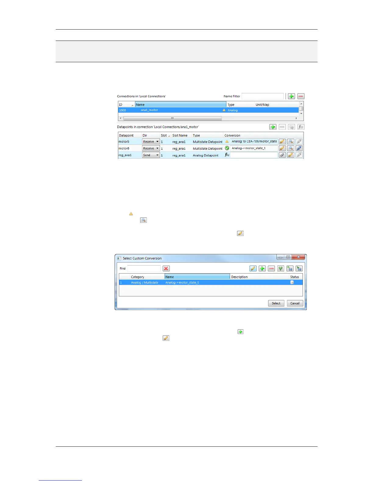
3. Now the connection tab contains the new connection and below the list of data points
in that connection as shown in Figure 15.
Figure 15: Connection tab with a connection and data points.
4. Change the direction by modifying Send or Receive. For changing multiple data points
use multi-select. Optionally, select Disable to temporarily exclude this data point from
communication in the connection.
5. If the attached data point needs conversion, the item displays a yellow exclamation
mark and the default conversion (e.g. ‘Analog to CEA-709/motor_state_t’). Click on
the button to view the current conversion.
6. To add a new conversion to this item, click on the button. A dialog opens, which
displays the matching adapters already available in the library as shown in Figure 16.
Figure 16: Choose a custom conversion.
7. Select an existing conversion, click the plus button to create a new conversion, or
click the edit button to modify an existing conversion.
8. An example for editing an analog to multi-state value conversion is shown in Figure
17. Enter a Conversion name, then edit the Value range from column and select the
desired Target state mapping.
 Loading...