L-VIS User Manual 45 LOYTEC
Version 6.2 LOYTEC electronics GmbH
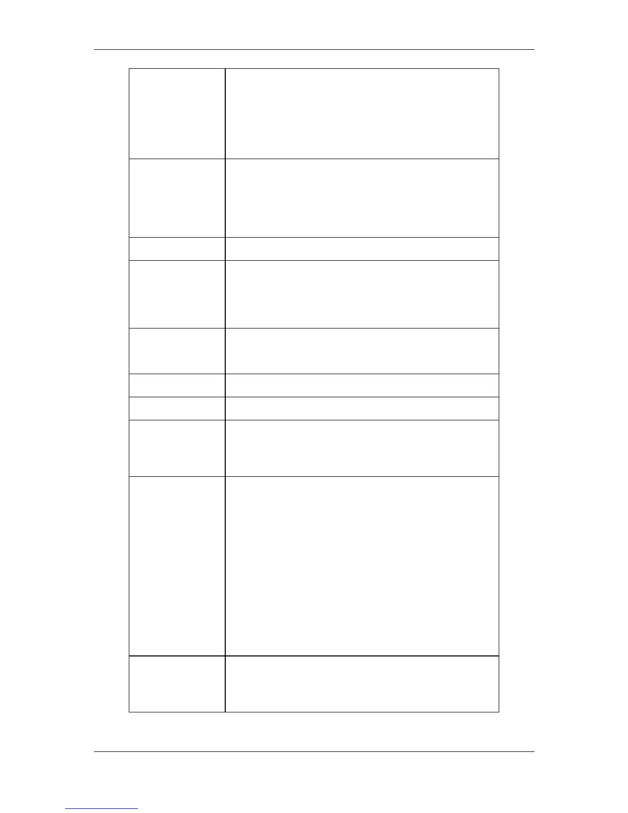
Pressing the Status button sends out a service pin message on the IP-
852 or the FT-10/LPT-10 channel (CEA-709 models) or send out an
‘I Am’ message (BACnet models).
To reset the device to factory defaults, hold the status button pressed
while the unit boots and release the button within a few seconds
when all interface LEDs light up orange.
Behind the small hole next to the status button is the reset button.
Use a pin to reach the reset button in order to hard-reset the device.
Doing this may cause trend log data or other persistent data to be
lost or reverted back to earlier data. To avoid data loss, reset the
device via the configuration software or the setup menu (command
page).
The power LED lights up green as soon as power is connected.
The status LED lights up red when the internal persistent storage
device is accessed. Also, on CEA-709 models operated on an FT-
10/LPT-10 channel, this LED indicates the node status. The LED is
off if the node is configured online and flashing red with a period of
1 Hz if the node is in the un-configured state.
This LED indicates incoming and outgoing data packets on the
currently active communications channel. Only packets which are
addressed to the device are shown.
The LINK ETH. LED indicates a successful Ethernet link.
The ACT ETH LED shows activity on the Ethernet network.
The ONLINE LED lights-up green if the node is in the configured
online state (CEA-709 models before firmware 4.0.0 only). Starting
with firmware 4.0.0, this LED indicates an active connection to the
built-in OPC server.
This LED either shows the current status of the IP-852 interface (in
IP-852 mode) or the status or the remote network interface, RNI (in
FT-10 mode).
IP-852: The LED lights green if the device is properly configured
and member of an IP-852 channel. The LED lights orange when the
device is configured in a channel but is waiting for updated channel
information from the configuration server. In case of errors, the
LED lights red.
RNI: The LED is dark if RNI is not supported by this device (older
devices do not have enough node IDs to support RNI). The LED is
green if the remote network interface is ready for connections and
orange if the device is currently in use. In case of errors, the LED is
red.
This LED shows the status of the MSTP interface, if the device is
operating in BACnet/MSTP mode. The LED is green for normal
operation, orange if there is no token and red if there are
communication errors.
Table 7: LEDs and Buttons